Table of Contents
Advertisement
Quick Links
Advertisement
Table of Contents

Related Manuals for UNEEKOR EYE XO2


Summary of Contents for UNEEKOR EYE XO2
- Page 1 INSTALLATION GUIDE EYE XO2 IMPORTANT: Read Before Using.
- Page 2 The plug must be plugged into a matching outlet that is properly installed and grounded in accordance with all local codes and ordinances. Step 1: Hardware Installation Guide Step 2: Software Installation Guide EYE XO2 I N STA LLAT I ON GUIDE...
-
Page 3: Table Of Contents
1. Installation Environment 2. Included Items 3. Hardware Install 3.1 Mounting Bracket 3.2 Slide Sensor 3.3 Connection 3.4 Connection Status 5. Software Install 13 - 20 6. Club Sticker Guide 21 - 27 EYE XO2 I N STA LLAT I ON GUIDE... -
Page 4: Warning: To Ensure Safe Use
Material damage refers to damage to home, furnishing, or anything within the unit’s vicinity. NEVER This symbol alerts the user to items that should never be carried out. EYE XO2 I N STA LLAT I ON GUIDE... - Page 5 Operating in a dark or cluttered space may lead to accidents. Be aware of your surroundings and use cautiously with children around. Swinging the club during play without being aware will result in serious injury or death. EYE XO2 I N STA LLAT I ON GUIDE...
-
Page 6: Installation Environment
Windows 10 (64bit) Version 1803 or higher Resolution 1920 x 1080 Connectivity Ethernet Port Required * AMD: 3rd gen Ryzen or higher and AMD Ryzen 3600 or higher (AMD 2700 is not compatible). EYE XO2 I N STA LLAT I ON GUIDE... -
Page 7: Included Items
Calibration Chart Power Cable Power Adapter Power Connector USB Ethernet Adapter M4 32mm screws Ethernet LAN Cable Level Club Stickers M6 15mm screws M6 15mm high screws M6 15mm low screws EYE XO2 I N STA LLAT I ON GUIDE... -
Page 8: Hardware Install
Failure may result in serious injury or CAUTION damage to property. Phillips M4 32mm Ladder Bracket Sensor Bar Screwdriver Screw x9 Necessary Tool Necessary Part(s) EYE XO2 I N STA LLAT I ON GUIDE... -
Page 9: Mounting Bracket
3.1 Hardware Install - Continued Step 1: Mount Bracket The EYE XO2 Sensor and bracket come attached together in the box. Slightly loosen the black M6 15 mm screws that are holding the sensor to the bracket so you can remove it. -
Page 10: Slide Sensor
M6 15mm screws are already screwed into the sensor. You can change this out with the M6 155 High or Low screws to adjust the angle/ tilt. M6 High 15mm M6 Low 15mm M6 15mm EYE XO2 I N STA LLAT I ON GUIDE... -
Page 11: Connection
Note: The plug must be plugged into a matching outlet that is properly installed and grounded in accordance with all local codes and ordinances. An extra green grounding wire is provided on the end of the power connector in case your outlet is not grounded. EYE XO2 I N STA LLAT I ON GUIDE... -
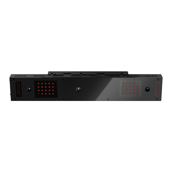
Page 12: Connection Status
Check and see if the power is on. You will see a bright red light on the switch of the sensor. Check and see if your EYE XO2 Sensor and PC are paired through the network. Please refer to our “Network Setup Guide” below to set the IP address. -
Page 13: Software Install
Failure to do will result in installation issues and slow gameplay. WARNING Please make sure the connection statuses are clear and everything is paired. Failure to do will result in installation issues. EYE XO2 I N STA LLAT I ON GUIDE... - Page 14 Please download it and save it to the Uneekor Folder Click here: EYE XO2 Installer Link Ctrl + Click the EYE XO2 Installer link above to begin EYE XO2 Installation or manually enter the URL: https://download.uneekor.com/dist/EYEXO2/Uneekor_EYEXO2_Setup.exe Under downloads you will see, “Uneekor_EYEXO2_Setup.exe” Click open file.
- Page 15 3.5 Software Install – Continued EYE XO2 Software Installation Keep the destination folder as “C:\Uneekor” and click Install. Please wait while installer completes installation. EYE XO2 I N STA LLAT I ON GUIDE...
- Page 16 3.6 Software Install – Continued EYE XO2 Software Installation **If these two pop-ups occur, please hit ok for both. The “Run Uneekor EYE XO2” is checked. Uncheck it and click finish EYE XO2 I N STA LLAT I ON GUIDE...
- Page 17 3.7 Software Install - Continued EYE XO2 Sensor Activation Go to the C: Drive-> Uneekor Folder -> Device -> Launch Monitor -> EYEXO Find and double click “EYEXO2_Check” Make sure the Sensor LAN connection is good before If you don’t get the Sensor LAN connection, please the software installation process.
- Page 18 3.8 Software Install - Continued EYE XO2 Network Config Once the sensor has been activated, you will have a screen like the one on the right. Click Set Network Param & Firewall to continue After the selection, you will be asked to restart the PC.
- Page 19 3.8 Software installation - Continued EYE XO2 Calibration To complete the installation of the EYE XO2. Follow the calibration guide linked below: EYE XO2 Calibration Guide EYE XO2 I N STA LLAT I ON GUIDE...
- Page 20 Click the “Show more” drop down and click “Keep anyway.” 3.8.3 Then click “Open file” under downloads. VIEW_SETUP 20220721 Setup” will “ open. Click “Next.” EYE XO2 I N STA LLAT I ON GUIDE EYE XO2 I N STA LLAT I ON GUIDE...
-
Page 21: Club Sticker Guide
Keep the Destination Folder as “C:\VIEW” and click “Install.” Check the “I agree” box and click “Install.” If a error pops up, click close and continue to VIEW Setup. Click “Start setup” EYE XO2 I N STA LLAT I ON GUIDE... - Page 22 Optional: If the C++ files are already installed on your PC, you may receive the error on the right Click Close and then next to continue EYE XO2 I N STA LLAT I ON GUIDE...
- Page 23 Click “Finish” Click “browse” and select the license file you saved in the Uneekor folder from the earlier steps, and click “Activation. Then click “Activate” VIEW Software installation is now complete. EYE XO2 I N STA LLAT I ON GUIDE...
- Page 24 Club Data Club Speed The speed of the club before impact. The amount of energy transferred from the club head to the golf ball. The angle difference between Face Angle and Club Path. EYE XO2 I NST ALLATI O N GUIDE...
- Page 25 Club Path is the directon (right or left) the club head is moving at impact and is measured relative to the target line. The direction (right or left) the club face is pointed at impact. It is measured relative to the target line. EYE XO2 I NS T ALLATIO N GUIDE...
- Page 26 Lie angle is the angle created between the center of the shaft and ground when you put your iron down in the address position. Vertical. Horizontal Where you strike the ball on the club face. EYE XO2 I NST ALLATIO N GUIDE...
- Page 27 EYE XO2 Club Sticker Placement EYE XO2 I NST ALLATI O N GUIDE...
- Page 28 Align the middle of the Bar Sticker to the horizontal center line or the 7th groove. Iron 13 groove 2. Dot Sticker Align to the middle of the bar sticker and parallel between the grooves. EYE XO2 I NST ALLATI O N GUIDE...
- Page 29 Bar Sticker can be placed inside he club face. *In the case where you do have to raise the horizontal line beyond the center to fit all 4 corners of the Bar Sticker, the data will be calculated higher. EYE XO2 INSTALLATION GUIDE...
- Page 30 *CLUB DATA CANNOT BE READ IF THE BALL IS COVERING ONE OF THE TWO STICKERS. CLUB DATA WILL BE ONLY SHOWN IF BOTH STICKERS ARE VISIBLE.* EYE XO2 INSTALLATION GUIDE...
- Page 31 Ball Speed Putter: 0.1 m/s ~ 30 m/s Measurement Range Ball Speed Driver/Iron: 5 m/s ~ 100 m/s Driver: -5 ~ 50 Degree Sensing Angle Iron: 0.1 ~ 80 Degree (shots over 60° can damage the unit) EYE XO2 INSTALLATION GUIDE...
- Page 32 MASTER YOUR PASSION Uneekor, Inc. 15770 Laguna Canyon Rd Suite 100 Irvine, CA 92618 sales@uneekor.com support@uneekor.com Uneekor © 2023 All Rights Reserved...
Need help?
Do you have a question about the EYE XO2 and is the answer not in the manual?
Questions and answers