Lenze IE2 m550-H Mounting And Switch-On Instructions
Three-phase ac motors version b
Hide thumbs
Also See for IE2 m550-H:
- Mounting and switch-on instructions (72 pages) ,
- Mounting and switch on instruction (76 pages)

Related Manuals for Lenze IE2 m550-H


Summary of Contents for Lenze IE2 m550-H
- Page 1 Mounting and switch-on instructions EN Three-phase AC motors IE2 three-phase AC motor m550-H Version B IE3 three-phase AC motor m550-P Version B...
-
Page 3: Table Of Contents
Contents Contents About this document Document description Further documents Notations and conventions Safety instructions Basic safety instructions Application as directed Foreseeable misuse Residual hazards Product information Identification of the products Nameplates Product codes Features Storage Mechanical installation Important notes Transport Preparation Installation Dimensions... - Page 4 Contents Technical data Standards and operating conditions Conformities and approvals Protection of persons and device protection EMC data Environmental conditions Rated data Ecodesign directive Environmental notes and recycling...
-
Page 5: About This Document
The documentation must always be complete and in a perfectly readable state. • Further documents Information and tools with regard to the Lenze products can be found on the Internet: www.Lenze.com à Downloads... -
Page 6: Notations And Conventions
About this document Notations and conventions Notations and conventions Conventions are used in this document to distinguish between different types of information. Numeric notation Decimal separator Point Generally shown as a decimal point. Example: 1 234.56 Warnings UL Warnings Are used in English and French. UR warnings Text Engineering Tools... -
Page 7: Safety Instructions
Safety instructions Safety instructions Disregarding the following basic safety measures and safety information may lead to severe personal injury and damage to property! Observe all specifications of the corresponding documentation supplied. This is the precondition for safe and trouble-free operation and for obtaining the product features specified. -
Page 8: Basic Safety Instructions
The procedural notes and circuit details described are only proposals. It is up to the user to check whether they can be adapted to the particular applications. Lenze does not take any responsibility for the suitability of the procedures and circuit proposals described. -
Page 9: Application As Directed
Safety instructions Application as directed Application as directed The harmonized standards of the series IEC/EN60034 are used. • The product must only be actuated under the operating conditions and power limits • specified in this documentation. The product meets the protection requirements of 2014/35/EU: Low-Voltage Directive. •... -
Page 10: Residual Hazards
Safety instructions Residual hazards Residual hazards Even if notes given are taken into consideration and protective measures are implemented, the occurrence of residual risks cannot be fully prevented. The user must take the residual hazards mentioned into consideration in the risk assessment for his/her machine/system. - Page 11 Safety instructions Residual hazards Motor protection Version with plug: • Never disconnect the plug when energized. The plug could be destroyed. Switch off the voltage supply or disable the inverter prior to disconnecting the plug. Installed thermal detectors are no full protection for the machine. •...
-
Page 12: Product Information
11.5 11.6 11.7 11.8 11.9 13.1 13.2 13.3 Position Contents Position Contents Manufacturer Motor code for Lenze frequency inverter Country of production Gearbox output data Approvals 13.1 Output torque Standards 13.2 Output speed Motor type 13.3 Load capacity Gearbox data... -
Page 13: Product Codes
Product information Identification of the products Product codes Product codes Motor product code Example Product type Motor Product family Generation Efficiency class Size Overall length Briefly Medium Long Number of poles 4-pole Degree of protection IP54/IP55 IP65/IP66 Cooling Self-ventilation Forced ventilation Brake Without Spring-applied brake... - Page 14 Product information Identification of the products Product codes Product code feedbacks Example 1024 Meaning Variant Product code Product family Resolver Resolver for safety function Incremental encoder Incremental encoder with commutation signal Singleturn absolute value encoder Multitum absolute value encoder Number 2-pole resolver for servo motors 2-pole resolver for three-phase AC motors Number of pole pairs for resolvers...
-
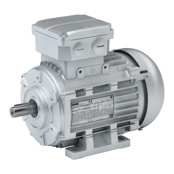
Page 15: Features
Product information Features Features The following figure provides an overview of the elements and connections on the product. Their position, size and appearance may vary. Motor connection Output flange Cooling Feedback Output shaft Brake Temperature monitoring Foot... -
Page 16: Storage
Storage Storage Storage up to one year: If possible, in the manufacturer's packaging • In dry, low-vibration environment without aggressive atmosphere • Protect against dust and impacts • Observe the climatic conditions according to the technical data • 4Environmental conditions ^ 43... -
Page 17: Mechanical Installation
• nameplate and in this documentation. Ambient media − especially chemically aggressive ones − may damage shaft sealing rings, • lacquers and plastics. Lenze offers special surface and corrosion protection in this case. • Transport Ensure appropriate handling. • Make sure that all component parts are securely mounted. Secure or remove loose •... -
Page 18: Installation
Mechanical installation Installation Installation The mounting surfaces must be plane, torsionally rigid and free from vibrations. • The mounting areas must be suited to absorb the forces and torques generated during • operation. Ensure an unhindered ventilation. • For versions with a fan, keep a minimum distance of 10 % from the outside diameter of the •... -
Page 19: Mounting
Mechanical installation Mounting Mounting Transmission elements Fit or remove transmission elements only using suitable equipment. • For fitting the transmission elements use the center hole in the shaft. • Avoid impacts and shocks. • In case of a belt drive, tension the belt in a controlled manner according to manufacturer •... -
Page 20: Product Extensions
Mechanical installation Mounting Product extensions Product extensions Assembly of lockable manual release lever in operating position Cheese head screw with hexagon nut Manual release lever Manual release shackle Fan cover Terminal block How to mount the manual release lever 1. Screw the cheese head screw with hexagon nut (1) loosely into the terminal block (3). 2. - Page 21 Mechanical installation Mounting Product extensions Handling of lockable manual release lever NOTICE ▶ Only lock the hand release in the service position for service work! ▶ The manual release must not be locked in the service position during operation, otherwise the brake could be damaged! ▶...
-
Page 22: Electrical Installation
(e.g. cable cross-sections, fuses, PE connection). The manufacturer of the system or machine is responsible for adherence to the limits • required in connection with EMC legislation. Preparation EMC-compliant wiring The EMC-compliant wiring is described in detail in the documentation of the Lenze inverters. -
Page 23: Motor Connection
Electrical installation Motor connection Motor connection To connect the motor correctly, you must follow: The notes in the terminal box of the motor. • The notes in the configuration document of the motor. • The technical data on the motor nameplate. •... -
Page 24: Connection Via Terminal Box
Electrical installation Motor connection Connection via terminal box Connection via terminal box Observe the notes on wiring, data on the nameplate, and the connection diagram in the terminal box. The connection must ensure a continuous and safe electrical supply: No protruding wire ends •... - Page 25 Electrical installation Motor connection Connection via terminal box Tightening torques for cover screw connections and cable glands The opening cutouts for the cable glands are closed with plugs. In the case of the blower terminal box, the opening is only arranged on one side.
- Page 26 Electrical installation Motor connection Connection via terminal box Power connection Bridge arrangement Y/Δ circuit Contact Name Meaning PE conductor Motor winding phase DC brake connection Contact Name Meaning Brake + Brake - Connection of brake AC Connection via rectifiers Contact Name Meaning Mains...
- Page 27 Electrical installation Motor connection Connection via terminal box Incremental encoder SinCos absolute value encoder with Hiperface© Contact Designation Meaning + UB Supply + Mass Track A/+COS A¯ Track A inverse/-COS Track B/+SIN B¯ Track B inverse/-SIN Zero track/+RS485 Z¯ Zero track inverse/-RS485 Incremental encoder shield Connection of temperature monitoring Contact...
-
Page 28: Connection Via Icn Connector
Electrical installation Motor connection Connection via ICN connector Connection via ICN connector Position of the connections Position Meaning Note ICN-M23 connector, 6-pole • Power connection • Brake connection • PE connection In addition to ICN-M23 connector , 8-pole: If feedback is present, the PT1000 temperature sensor is wired in •... - Page 29 Electrical installation Motor connection Connection via ICN connector Feedback and temperature monitoring connection ICN-M23 connector assignment Resolvers Contact Name Meaning + Ref Code 0° Transformer windings - Ref Supply: Electronic nameplate +VCC ENP (Only for motors and inverters which support this function) + Cos Stator windings cosine...
- Page 30 Electrical installation Motor connection Connection via ICN connector Assembly of ICN connectors NOTICE Live cables! Possible destruction of the connector. ▶ Never remove connector when voltage is being applied! ▶ Disable inverter before removing the connector! NOTICE Loss of the protection class due to incorrect mounting! Malfunctions may occur.
-
Page 31: Connection Via Han Connector
Electrical installation Motor connection Connection via HAN connector Connection via HAN connector The power, brake and temperature monitoring can be connected in the HAN connector. The designs HAN 10E or HAN modular with two power modules (16 A or 40 A) are available. The HAN 10E connector is only available for motors with the connection method Y/Δ. -
Page 32: Connection Via M12 Connector
Electrical installation Motor connection Connection via M12 connector HAN modular 16 A pin assignment Module Contact Name Meaning Illustration Motor winding phase Blank module Temperature monitoring +PT1000 +/AC Brake -/AC Switching contact Rectifier Temperature monitoring -PT1000 HAN modular 40 A pin assignment Module Contact Name... -
Page 33: Commissioning
Default Ambient temperature 0 °C … +40 °C Note At an ambient temperature generally over +30 °C: • A check of the application case by Lenze is required. Deep-freeze Ambient temperature -30 °C … +10 °C Note When starting a cold motor at below -20 °C, you have to expect an increased starting torque on account of the higher viscosity of the roller bearing grease. -
Page 34: Before Initial Switch-On
Commissioning Before initial switch-on Before initial switch-on That the drive does not show any visible signs of damage. • Is the mechanical fixing o.k.? • Is the electrical connection ok? • Are all rotating parts and surfaces that may become hot protected against contact? •... -
Page 35: Maintenance
Any work on the safety encoder which has not been executed professionally will cause a loss of the safety functions. Possible consequences: damage to property and/or injury to persons. ▶ The safety encoder may only be repaired or replaced by the Lenze service or its authorised persons. Maintenance intervals... -
Page 36: Maintenance Work
Maintenance Maintenance work Maintenance work Maintenance work at the spring-applied brake NOTICE ▶ Brakes with defective armature plates, springs or flanges must be completely replaced. ▶ Before carrying out maintenance work, identify the brake and motor protection type from the nameplate. 4Nameplates ^ 12 Before working on the brake, remove the integral fan cover or blower cover on... - Page 37 Maintenance Maintenance work Check and adjust air gap DANGER! Risk of injury due to rotary parts. ▶ The motor must not be running when checking the air gap. Spring-applied brake ABR IP65/66 Spring-applied brake HBR IP54/55 Spring-applied brake ABR IP54/55 Stator Sleeve bolt with hexagon Armature plate...
- Page 38 Maintenance Maintenance work 4. Measure the air gap s between stator (1) and armature plate (2) in the vicinity of the cap screws (3) using a surface feeler gauge. NOTICE ▶ With the holding brake HBR and application brake ABR (motor protection class IP65/66) the air gap cannot be adjusted! If the air gap s is reached, the brakes must be replaced.
-
Page 39: Repair
First check the possible causes of malfunction according to the 4Diagnostics and fault • elimination ^ 40 If the fault cannot be remedied using one of the measures listed, please contact the Lenze • service department. The contact data can be found on the rear of this documentation. -
Page 40: Diagnostics And Fault Elimination
Adjust rated operating mode to the specified • Externally ventilated or self-ventilated motors 60034-1) exceeded operating conditions. Determination of correct > 110 °C drive by expert or Lenze customer service Loose contact in supply cable (temporary Tighten loose contact single-phase operation!) Fuse has blown (single-phasing!) - Page 41 Diagnostics and fault elimination Malfunctions For resistance measurement, observe the data on the brake nameplate. Trouble Possible cause Remedy Brake does not release, Coil is interrupted Measure the resistance of the coil with a multimeter: Air gap is not zero •...
-
Page 42: Technical Data
Technical data Standards and operating conditions Conformities and approvals Technical data Standards and operating conditions Conformities and approvals Conformities 2006/42/EC Machinery Directive, only relevant for (permissible) safety components, such as encoder or brake 2009/125/EC ErP Directive and associated regulations on the ecodesign of electric motors 2011/65/EU RoHS Directive 2014/30/EU... -
Page 43: Environmental Conditions
Technical data Standards and operating conditions Environmental conditions Environmental conditions Energy efficiency High efficiency Class IE2 EN 60034-30-1 Premium high Class IE3 efficiency Climate Storage EN 60721-3-1 1K3 (-25 ... +60°C) Transport EN 60721-3-2 2K3 (-25 ... +70°C) EN 60721-3-3 3K3 (0 ... -
Page 44: Rated Data
Technical data Rated data Rated data Rated data 50 Hz Motor M55BH 063S04 063M04 063L04 071M04 071L04 Rated power 0.12 0.18 0.25 0.37 0.55 rated Rated speed 1415 1400 1390 1425 1430 rated Max. speed 4500 4500 4500 4500 4500 max. - Page 45 Technical data Rated data Motor M55BP 080M04 090M04 090L04 100M04 100L04 112M04 Rated power 0.75 rated Rated speed 1455 1465 1465 1470 1470 1470 rated Max. speed 4500 4500 4500 4500 4500 4500 max. Rated voltage Dreieck rated, Δ Stern rated, Y Rated current 230 V...
- Page 46 Technical data Rated data Rated data 60 Hz Motor M55BH 063S04 063M04 063L04 071M04 071L04 Rated power 0.12 0.18 0.25 0.37 0.55 rated Rated speed 1725 1715 1710 1735 1740 rated Max. speed 4500 4500 4500 4500 4500 max. Rated voltage Stern rated, Y Rated current...
- Page 47 Technical data Rated data Motor M55BP 080M04 090M04 090L04 100M04 100L04 112M04 Rated power 0.75 rated Rated speed 1760 1770 1770 1775 1770 1775 rated Max. speed 4500 4500 4500 4500 4500 4500 max. Rated voltage Stern rated, Y Rated current 460 V 1.40 2.02...
- Page 48 Technical data Rated data Rated data 87 Hz Motor M55BH 063S04 063M04 063L04 071M04 071L04 Rated power 0.21 0.33 0.45 0.66 rated Rated speed 2525 2505 2500 2535 2540 rated Max. speed 4500 4500 4500 4500 4500 max. Max. torque 3.20 4.90 6.90...
- Page 49 Technical data Rated data Motor M55BP 080M04 090M04 090L04 100M04 100L04 112M04 Rated power 1.35 7.35 rated Rated speed 2565 2575 2575 2580 2580 2580 rated Max. speed 4500 4500 4500 4500 4500 4500 max. Max. torque 19.7 28.7 39.1 57.2 78.0 max.
-
Page 50: Ecodesign Directive
Year of manufacture Year and week of manufacture: 4Nameplates ^ 12 Name or trademark, official registration number, and manufacturer's place of establishment Lenze Drives GmbH HR Lemgo B 6478 Breslauer Strasse 3 D-32699 Extertal GERMANY Model number of the product... - Page 51 Year of manufacture Year and week of manufacture: 4Nameplates ^ 12 Name or trademark, official registration number, and manufacturer's place of establishment Lenze Drives GmbH HR Lemgo B 6478 Breslauer Strasse 3 D-32699 Extertal GERMANY Model number of the product...
- Page 52 Year of manufacture Year and week of manufacture: 4Nameplates ^ 12 Name or trademark, official registration number, and manufacturer's place of establishment Lenze Drives GmbH HR Lemgo B 6478 Breslauer Strasse 3 D-32699 Extertal GERMANY Model number of the product...
-
Page 53: Environmental Notes And Recycling
Lenze products and their packaging: Lenze products are subject in part to EU Directive 2011/65/EU on the restriction of the use of certain hazardous substances in electrical and electronic devices (RoHS). This is documented accordingly in the EU Declaration of Conformity and with the CE mark. - Page 56 © 05/2020 | | 2.0 Lenze Drives GmbH Postfach 101352, 31763 Hameln Breslauer Straße 3, 32699 Extertal GERMANY HR Lemgo B 6478 Phone +49 5154 82-0 Fax +49 5154 82-2800 sales.de@lenze.com www.Lenze.com Lenze Service GmbH Breslauer Straße 3, 32699 Extertal...
Need help?
Do you have a question about the IE2 m550-H and is the answer not in the manual?
Questions and answers