Table of Contents
Advertisement
Quick Links
Advertisement
Table of Contents

Related Manuals for Lenze IE3 g500-H


Summary of Contents for Lenze IE3 g500-H
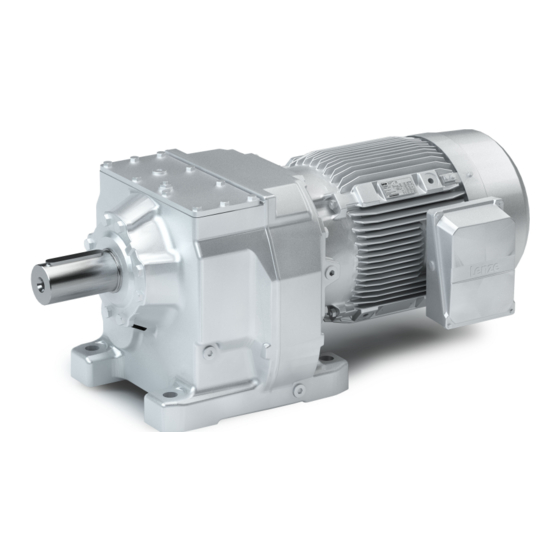
- Page 1 Project planning EN Geared motors IE3 g500-H / m540-P helical geared motor...
-
Page 3: Table Of Contents
Contents Contents About this document Document description Further documents Notations and conventions Product information Product description Identification of the products Features The modular system Designs Mounting positions Information on project planning Safety instructions Basic safety instructions Application as directed Foreseeable misuse Residual hazards General information Drive dimensioning... - Page 4 Contents Technical data Notes regarding the given data Standards and operating conditions Conformities and approvals Protection of persons and device protection EMC data Environmental conditions Data overview Gearboxes with adapter Radial forces and axial forces Selection tables Motor – inverter assignment Dimensions Basic dimensions Additional lengths...
-
Page 5: About This Document
Please observe the notes in the following chapters! ▶ Safety instructions ^ 14 ▶ Information on mechanical installation ^ 32 ▶ Information on electrical installation ^ 33 Further documents Information and tools with regard to the Lenze products can be found on the Internet: www.Lenze.com à Downloads... -
Page 6: Notations And Conventions
About this document Notations and conventions Notations and conventions Conventions are used in this document to distinguish between different types of information. Numeric notation Decimal separator Point Generally shown as a decimal point. Example: 1 234.56 Warnings UL Warnings Are used in English and French. UR warnings Text Engineering Tools... -
Page 7: Product Information
• Three-phase AC motors for mains and inverter operation In a power range from 1.5 to 55 kW, Lenze offers inverter-compatible three-phase AC motors in accordance with the Ecodesign Directive for more extensive tasks. These motors have efficiency class IE3 and can be used for the versions required for open-loop or closed-loop inverter operation. -
Page 8: Identification Of The Products
Identification of the products Flexible in motor mounting For motor mounting, Lenze offers a scalable modular system of gearboxes with adapters. Power is transmitted between the motor and gearbox via a flexible jaw coupling or a plug-in hollow shaft. The shaft holders are available for motor shafts with or without featherkey, depending on the design. -
Page 9: Features
Product information Features Features The following figure provides an overview of the elements and connections on the product. Their position, size and appearance may vary. Temperature monitoring Ventilation (depending on the mounting position) Brake Oil filler plug (depending on the mounting position) Feedback Cooling Output shaft... -
Page 10: The Modular System
Product information The modular system The modular system Values printed in bold are standard designs. Values that are not printed in bold are potential extensions, some of them including a surcharge. Geared motors 5000 Nm to 14000 Nm Gearbox g500-H5000 g500-H8000 g500-H14000 Min. -
Page 11: Designs
Product information The modular system Designs Designs Gearbox versions Observe the available gearbox designs! 4The modular system ^ 10 Solid shaft with foot Without centering (VBR) Solid shaft without foot With centering (VCR) Flange with through holes (VCK) -
Page 12: Mounting Positions
Product information The modular system Mounting positions Mounting positions Details of the mounting position are needed to ensure the corresponding lubricant amount, position of the ventilation, oil checks and oil drain plug on the gearbox. M1 [ A ] M6 [ ... - Page 13 Product information The modular system Mounting positions Positions of the terminal boxes/connectors Power terminal box Blower terminal box HAN connector with/without ICN connector with/without ICN connector Positions of the connections HAN connector Position of the manual release lever...
-
Page 14: Information On Project Planning
Information on project planning Safety instructions Information on project planning Safety instructions Disregarding the following basic safety measures and safety information may lead to severe personal injury and damage to property! Observe all specifications of the corresponding documentation supplied. This is the precondition for safe and trouble-free operation and for obtaining the product features specified. -
Page 15: Basic Safety Instructions
The procedural notes and circuit details described are only proposals. It is up to the user to check whether they can be adapted to the particular applications. Lenze does not take any responsibility for the suitability of the procedures and circuit proposals described. -
Page 16: Application As Directed
Information on project planning Safety instructions Application as directed Application as directed The product must only be actuated under the operating conditions and power limits • specified in this documentation. The product meets the protection requirements of 2014/35/EU: Low-Voltage Directive. •... -
Page 17: Residual Hazards
Information on project planning Safety instructions Residual hazards Residual hazards Even if notes given are taken into consideration and protective measures are implemented, the occurrence of residual risks cannot be fully prevented. The user must take the residual hazards mentioned into consideration in the risk assessment for his/her machine/system. - Page 18 Information on project planning Safety instructions Residual hazards Gearbox protection Excessively high torques cause damage to the gearbox. • Do not exceed the output torque specified on the nameplate. Excessively high input speeds lead to higher temperatures. • Do not exceed the input speed specified on the nameplate. Lateral forces on the gearbox shaft are possible.
-
Page 19: General Information
Information on project planning General information General information Operation with mains power If operated with mains power, the three-phase AC motor starts up in accordance with the speed-torque characteristic when switched on. It follows this characteristic until it reaches its stable operating point. - Page 20 Operation with blower Operation below 5 Hz is possible depending on the application and the control method. Verification of the application by Lenze required. Thermal power limit The thermal power limit, defined by the heat balance, limits the permissible continuous gearbox power.
- Page 21 Information on project planning General information NOTICE A thermal check with the Drive Solution Designer (DSD) or contacting your Lenze representative is required if ▶ the input speed n > 1500 rpm is exceeded in case of the gearbox ratios given in the following.
-
Page 22: Drive Dimensioning
With the «Drive Solution Designer«, you can design the drive both quickly and to a high quality. The software contains profound and proven expertise with regard to drive applications and mechatronic drive components. Please get in touch with your Lenze representative. Operation chart Mains operation... - Page 23 Information on project planning Drive dimensioning Define required input variables Necessary input variables Note Symbol Unit Operating time / day Ambient temperature °C Site altitude amsl Radial force Axial force Transmission element at the output Gear wheels, sprockets … Effective diameter of the transmission element Load torque For short-term load peaks L,max...
- Page 24 Information on project planning Drive dimensioning Gearbox efficiency Gearboxes Gearbox efficiency η g500-H 2-stage 0.96 3-stage 0.95 4-stage 0.94 Determine product on the basis of the forces Transmission element Gear wheels Sprockets Toothed belt pulleys Narrow V-belt (depending on the (depending on the pretension) pretension)
- Page 25 Information on project planning Drive dimensioning Application factor k 24 h 16 h 8 h 1000 1200 1400 1600 1/h Application factor Switching rate Ratio of motor stalling torque/rated torque < 2.5 Ratio of motor stalling torque/rated torque ≥ 2.5 Stalling/rated motor torque 4Rated data ^ 100...
- Page 26 Information on project planning Drive dimensioning Inverter operation Selection table Check Unit Note Rated frequency 50/87 ≥ P Rated power rated ≥ M The geared motor must be able to provide Output torque enough torque for M L,max Max. Output speed ≈...
-
Page 27: Final Configuration
Information on project planning Final configuration Surface and corrosion protection Final configuration Screening Connection dimensions Output shaft Output flange/foot Mounting position Geared motor Connector/terminal box Driven shaft/output flange Product extensions Torque plate Shaft cover Connector/terminal box Brake Feedback Blower Temperature monitoring Second shaft end Handwheel Protection cover... -
Page 28: Lubricants
Information on project planning Final configuration Lubricants Lubricants Lubricant CLP 220 CLP 460 Ambient temperature 0 ... +40 °C Specification Mineral oil with EP additives Changing interval Operating hours 16000 Not later than after 3 years At oil temperature 80 °C Manufacturer Fuchs Klüber... -
Page 29: Ventilation
Information on project planning Final configuration Ventilation Ventilation NOTICE ▶ For gearboxes with ventilation, a gap of at least 30 mm has to be observed to the machine wall on the corresponding gearbox side. g500-H5000 ... H14000 Mounting position M1 (A) Mounting position M2 (D) Mounting position M3 (B) Filling and ventilation... - Page 30 Information on project planning Final configuration Ventilation Mounting position M4 (C) Mounting position M5 (F) Mounting position M6 (E) Filling and ventilation Check Drain ② 2-stage gearboxes ③ 3-stage gearboxes Gearbox with oil compensation reservoir for mounting position M4 (C) In order to guarantee a reliable lubrication of the toothed parts in mounting position M4 (C) (motor is on the gearbox vertical from the top), a high filling level is required in the gearbox.
- Page 31 Information on project planning Final configuration Ventilation Dimensions of oil compensation reservoir Gearbox g500-H5000 g500-H8000 g500-H14000...
-
Page 32: Information On Mechanical Installation
• nameplate and in this documentation. Ambient media − especially chemically aggressive ones − may damage shaft sealing rings, • lacquers and plastics. Lenze offers special surface and corrosion protection in this case. • Transport Ensure appropriate handling. • Make sure that all component parts are securely mounted. Secure or remove loose •... -
Page 33: Information On Electrical Installation
Use of filters, chokes • Use of special motor cables • Preparation The notes for the electrical connection can be found in the enclosed mounting instructions. EMC-compliant wiring The EMC-compliant wiring is described in detail in the documentation of the Lenze inverters. -
Page 34: Technical Data
The ratings apply to the operating mode S1 (acc. to EN 60034). • NOTICE In case of other operating conditions, the achievable values can differ for those mentioned. ▶ In case of extreme operating conditions, please get in touch with your Lenze representative. -
Page 35: Standards And Operating Conditions
USA and Canada File No. E508568 for USA and Canada (requirements of the CSA cURus UL 1004-1 22.2 No. 100) servo motor, Lenze File No. E210321 GB 12350 GB Standard: Safety requirements of small-power motors CSA 22.1 No. 100... -
Page 36: Data Overview
Technical data Data overview Data overview The following tables contain the most important data of the gearbox with the attachable motors of a geared motor. The data given for speed, torque and power are valid if the input speed n = 1400 rpm •... - Page 37 Technical data Data overview g500-H5000, 3-stage gearboxes Output speed Max. output Ratio Number of teeth Max. backlash torque Standard 2, max 23.5 5000 62.664 21995 21.3 5000 68.658 61586 18.5 5000 78.777 193556 2457 16.3 5000 89.909 241945 2691 14.4 5000 102.053 83581...
- Page 38 Technical data Data overview g500-H8000, 3-stage gearboxes Output speed Max. output Ratio Number of teeth Max. backlash torque Standard 2, max 52.4 8000 28.128 40223 1430 42.8 8000 34.307 86797 2530 37.3 8000 39.407 91031 2310 33.9 8000 43.511 55042 1265 30.0 8000...
- Page 39 Technical data Data overview g500-H14000, 3-stage gearboxes Output speed Max. output Ratio Number of teeth Max. backlash torque Standard 2, max 51.7 14000 28.406 102973 3625 40.6 14000 36.331 340603 9375 35.6 14000 41.433 134657 3250 32.7 14000 45.060 111072 2465 25.6 14000...
-
Page 40: Gearboxes With Adapter
Technical data Gearboxes with adapter Gearboxes with adapter Versions with jaw coupling Adapter Spider Coupling hub Power is transmitted between the motor and gearbox via a jaw coupling. The gearbox shaft is designed as a claw on the motor side. The counterpart, the coupling hub, is placed on the motor shaft and secured axially. - Page 41 Technical data Gearboxes with adapter Dimensions of gearbox with adapter for IEC standard motors Gearbox dimensions 4Basic dimensions ^ 67 Versions with jaw coupling Motor Adapter Gearbox g500 Size Shaft Size -H5000 -H8000 -H14000 FT165 FT215 FF265 11.0 FT300 15.0 18.5 FT300 22.0...
- Page 42 Technical data Gearboxes with adapter Dimensions of gearbox with adapter for NEMA motors Gearbox dimensions 4Basic dimensions ^ 67 Versions with jaw coupling Motor Adapter Gearbox g500 Size Shaft Size -H5000 -H8000 -H14000 inch inch inch 143/145 TC 0.875 2.250 5.875 182/184 TC 1.125...
- Page 43 Technical data Gearboxes with adapter Dimensions of gearboxes with adapter for servo motors Gearbox dimensions 4Basic dimensions ^ 67 Versions with jaw coupling Motor Adapter Gearbox g500 Shaft Size -H5000 -H8000 -H14000 FT130 FT165 FT215 FT300 FT350...
-
Page 44: Radial Forces And Axial Forces
Technical data Radial forces and axial forces Radial forces and axial forces Permissible radial force The calculation of the permissible radial force must take account of the additional load factor rad, perm rad,max Permissible axial force If there is no radial force, the maximum axial force is 50% of the value in the table F rad,max = 0.5 x F ax, zul... - Page 45 1.3 and an input speed of 1400 rpm. In case of different operating conditions, considerably higher forces can be transmitted. Please get in touch with your Lenze representative Max. radial force, gearbox with foot (VBR) Output speed n...
- Page 46 Technical data Radial forces and axial forces Max. radial force, gearbox with/without foot with threaded pitch circle (V□R/V□K) Output speed n [rpm] Getriebe Max. radial force F rad,max g500-H5000 11000 13000 13500 13500 13500 13500 g500-H8000 23000 25000 25000 25000 25000 25000 g500-H14000...
-
Page 47: Selection Tables
5 Hz to 50 or 87 Hz: Operation at constant torque. Below 20 Hz (n ): Derating without separate fan. Below 5 Hz (n ): Verification of the application by Lenze required. Below 5 Hz (n ): Verification of the application by Lenze required. Notes on the selection tables The selection tables represent the available combinations of gearbox, number of stages, ratio and motor for the mounting position M1. - Page 48 Technical data Selection tables 50 Hz: 1.5 kW 87 Hz: 2.6 kW Inverter operation Geared motor 5 Hz - - 20 Hz 50 Hz (1:10) 87 Hz (1:17.4) kgcm² 1240 11.0 1240 19.5 1240 65.000 130.842 g500-H5000 m540-P90/L4 1378 1378 17.6 1378 63.000...
- Page 49 Technical data Selection tables 50 Hz: 3 kW 87 Hz: 5.2 kW Inverter operation Geared motor 5 Hz - - 20 Hz 50 Hz (1:10) 87 Hz (1:17.4) kgcm² 15.5 30.9 54.5 152.000 47.175 g500-H5000 m540-P100/L4 14.5 29.0 51.1 151.000 50.326 g500-H5000 m540-P100/L4...
- Page 50 Technical data Selection tables 50 Hz: 4 kW 87 Hz: 7.35 kW Inverter operation Geared motor 5 Hz - - 20 Hz 50 Hz (1:10) 87 Hz (1:17.4) kgcm² 21.8 43.6 76.7 190.000 33.519 g500-H5000 m540-P112/M4 19.7 39.3 69.2 187.000 37.147 g500-H5000 m540-P112/M4...
- Page 51 Technical data Selection tables 50 Hz: 5.5 kW 87 Hz: 9.6 kW Inverter operation Geared motor 5 Hz - - 20 Hz 50 Hz (1:10) 87 Hz (1:17.4) kgcm² 27.9 55.9 98.1 368.000 26.305 g500-H5000 m540-P132/M4 24.7 1029 49.5 1029 86.9 1029 365.000...
- Page 52 Technical data Selection tables Inverter operation Geared motor 5 Hz - - 20 Hz 50 Hz (1:10) 87 Hz (1:17.4) kgcm² 4970 9027 9027 9027 350.000 264.509 g500-H8000 m540-P132/M4 5099 9263 9263 9263 363.000 271.398 g500-H14000 m540-P132/M4 5280 9592 9592 9592 349.000 281.041...
- Page 53 Technical data Selection tables 50 Hz: 7.5 kW 87 Hz: 13.1 kW Inverter operation Geared motor 5 Hz - - 20 Hz 50 Hz (1:10) 87 Hz (1:17.4) kgcm² 39.5 78.8 507.000 18.599 g500-H5000 m540-P132/L4 35.0 69.8 500.000 20.978 g500-H5000 m540-P132/L4 31.4 1110...
- Page 54 Technical data Selection tables Inverter operation Geared motor 5 Hz - - 20 Hz 50 Hz (1:10) 87 Hz (1:17.4) kgcm² 4981 9058 9058 13.3 9058 500.000 193.751 g500-H14000 m540-P132/L4 5019 9127 9127 13.2 9127 476.000 195.242 g500-H8000 m540-P132/L4 5670 10312 10312 1.4 11.7...
- Page 55 Technical data Selection tables 50 Hz: 11 kW 87 Hz: 19.2 kW Inverter operation Geared motor 5 Hz - - 20 Hz 50 Hz (1:10) 87 Hz (1:17.4) kgcm² 11.1 56.6 908.000 13.073 g500-H5000 m540-P160/M4 10.0 51.3 899.000 14.435 g500-H5000 m540-P160/M4 45.1 1134...
- Page 56 Technical data Selection tables Inverter operation Geared motor 5 Hz - - 20 Hz 50 Hz (1:10) 87 Hz (1:17.4) kgcm² 4182 7602 13.2 7602 23.1 7602 915.000 111.686 g500-H14000 m540-P160/M4 4608 8375 12.0 8375 21.0 8375 861.000 123.043 g500-H8000 m540-P160/M4 4692 8528...
- Page 57 Technical data Selection tables 50 Hz: 15 kW 87 Hz: 26.3 kW Inverter operation Geared motor 5 Hz - - 20 Hz 50 Hz (1:10) 87 Hz (1:17.4) kgcm² 21.4 4.7 1081.000 6.789 g500-H5000 m540-P160/L4 19.3 98.7 4.3 1070.000 7.497 g500-H5000 m540-P160/L4 17.0...
- Page 58 Technical data Selection tables Inverter operation Geared motor 5 Hz - - 20 Hz 50 Hz (1:10) 87 Hz (1:17.4) kgcm² 3508 10.8 6378 21.5 6378 37.6 6378 1.2 1060.000 68.712 g500-H8000 m540-P160/L4 3874 7043 19.4 7043 34.1 7043 1.1 1053.000 75.868 g500-H8000 m540-P160/L4...
- Page 59 Technical data Selection tables 50 Hz: 18.5 kW 87 Hz: 32.2 kW Inverter operation Geared motor 5 Hz - - 20 Hz 50 Hz (1:10) 87 Hz (1:17.4) kgcm² 29.9 4.8 1451.000 4.846 g500-H5000 m540-P180/M4 24.5 4.4 1412.000 5.911 g500-H5000 m540-P180/M4 21.4 3.8 1391.000...
- Page 60 Technical data Selection tables 50 Hz: 22 kW 87 Hz: 38.5 kW Inverter operation Geared motor 5 Hz - - 20 Hz 50 Hz (1:10) 87 Hz (1:17.4) kgcm² 29.9 4.1 1551.000 4.846 g500-H5000 m540-P180/L4 24.5 3.7 1512.000 5.911 g500-H5000 m540-P180/L4 24.3 4.9 1637.000...
- Page 61 Technical data Selection tables Inverter operation Geared motor 5 Hz - - 20 Hz 50 Hz (1:10) 87 Hz (1:17.4) kgcm² 8392 15258 13.2 15258 0.9 23.1 15258 0.9 1485.000 111.686 g500-H14000 m540-P180/L4 9413 17115 11.7 17115 0.8 20.6 17115 0.8 1474.000 125.283 g500-H14000 m540-P180/L4...
- Page 62 Technical data Selection tables 50 Hz: 30 kW 87 Hz: 52.5 kW Inverter operation Geared motor 5 Hz - - 20 Hz 50 Hz (1:10) 87 Hz (1:17.4) kgcm² 29.9 3.0 2351.000 4.846 g500-H5000 m540-P200/M4 27.7 4.1 2473.000 5.229 g500-H8000 m540-P200/M4 24.5 1117...
- Page 63 Technical data Selection tables 50 Hz: 37 kW 87 Hz: 64.8 kW Inverter operation Geared motor 5 Hz - - 20 Hz 50 Hz (1:10) 87 Hz (1:17.4) kgcm² 35.5 4.3 4632.000 4.088 g500-H8000 m540-P225/M4 29.9 1124 1124 1124 2.4 4351.000 4.846 g500-H5000 m540-P225/M4...
- Page 64 Technical data Selection tables 50 Hz: 45 kW 87 Hz: 78.7 kW Inverter operation Geared motor 5 Hz - - 20 Hz 50 Hz (1:10) 87 Hz (1:17.4) kgcm² 35.5 1154 1154 1154 3.5 5132.000 4.088 g500-H8000 m540-P225/L4 31.0 1320 1320 1320 4.9 5468.000...
- Page 65 Technical data Selection tables 50 Hz: 55 kW 87 Hz: 87 kW Inverter operation Geared motor 5 Hz - - 20 Hz 50 Hz (1:10) 87 Hz (1:17.4) kgcm² 35.5 1404 1404 1269 3.2 8932.000 4.088 g500-H8000 m540-P250/M4 31.0 1606 1606 1452 4.5 9268.000...
-
Page 66: Motor - Inverter Assignment
Technical data Motor – inverter assignment Motor – inverter assignment Rated frequency 50/60 Hz Rated power Motor Inverter m540-P90/L4 E84AVXXX1524 m540-P100/M4 E84AVXXX2224 m540-P100/L4 E84AVXXX3024 m540-P112/M4 E84AVXXX4024 m540-P132/M4 E84AVXXX5524 m540-P132/L4 E84AVXXX7524 m540-P160/M4 E84AVXXX1134 m540-P160/L4 E84AVXXX1534 18.5 m540-P180/M4 E84AVXXX1834 m540-P180/L4 E84AVXXX2234 m540-P200/M4 E84AVXXX3034 m540-P225/M4 E84AVXXX3734... -
Page 67: Dimensions
Technical data Dimensions Basic dimensions Dimensions Basic dimensions Notes on the basic dimensions The following legend shows the layout of the dimension tables: Motor m540-P 90/L4 100/M4 100/L4 Table content Explanation Total length Total length of the drive without brake/feedback Motor length Length of the motor without brake/feedback Motor diameter... - Page 68 Technical data Dimensions Basic dimensions g500-H5000, 2-/3-stage Gearbox design: Solid shaft with foot (VBR) Motor series m540-P Motor 090M4 100M4 112M4 132M4 160M4 160L4 180M4 180L4 200M4 225M4 225L4 250M4 090L4 100L4 132L4 Total length 1041 1067 1127 1127 Motor length Motor diameter Motor/connection distance Δ...
- Page 69 Technical data Dimensions Basic dimensions g500-H5000, 2-/3-stage Gearbox design: Solid shaft with centering (VCR) Motor series m540-P Motor 090M4 100M4 112M4 132M4 160M4 160L4 180M4 180L4 200M4 225M4 225L4 250M4 090L4 100L4 132L4 Total length 1041 1067 1127 1127 Motor length Motor diameter Motor/connection distance Δ...
- Page 70 Technical data Dimensions Basic dimensions g500-H5000, 2-/3-stage Gearbox design: Solid shaft with flange (VCK) Motor series m540-P Motor 090M4 100M4 112M4 132M4 160M4 160L4 180M4 180L4 200M4 225M4 225L4 250M4 090L4 100L4 132L4 Total length 1041 1067 1127 1127 Motor length Motor diameter Motor/connection distance Δ...
- Page 71 Technical data Dimensions Basic dimensions g500-H8000, 2-/3-stage Gearbox design: Solid shaft with foot (VBR) Motor series m540-P Motor 112M4 100M4 132M4 160M4 160L4 180M4 180L4 200M4 225M4 225L4 250M4 100L4 132L4 Total length 1011 1074 1095 1155 1206 Motor length Motor diameter Motor/connection distance Δ...
- Page 72 Technical data Dimensions Basic dimensions g500-H8000, 2-/3-stage Gearbox design: Solid shaft with flange (VCK) Motor series m540-P Motor 112M4 100M4 132M4 160M4 160L4 180M4 180L4 200M4 225M4 225L4 250M4 100L4 132L4 Total length 1011 1074 1095 1155 1206 Motor length Motor diameter Motor/connection distance Δ...
- Page 73 Technical data Dimensions Basic dimensions g500-H14000, 2-/3-stage Gearbox design: Solid shaft with foot (VBR) Motor series m540-P Motor 112M4 132M4 160M4 160L4 180M4 180L4 200M4 225M4 225L4 250M4 132L4 Total length 1035 1048 1078 1141 1160 1220 1268 Motor length Motor diameter Motor/connection distance Δ...
- Page 74 Technical data Dimensions Basic dimensions g500-H14000, 2-/3-stage Gearbox design: Solid shaft with flange (VCK) Motor series m540-P Motor 112M4 132M4 160M4 160L4 180M4 180L4 200M4 225M4 225L4 250M4 132L4 Total length 1035 1048 1078 1141 1160 1220 1268 Motor length Motor diameter Motor/connection distance Δ...
-
Page 75: Additional Lengths
Technical data Dimensions Additional lengths Additional lengths Self-ventilated motors Motor m540-P 90/L4 100/M4 112/M4 132/M4 160/M4 180/M4 100/L4 132/L4 160/L4 180/L4 With feedback Δ L [mm] 92.5 93.5 95.0 95.0 95.0 95.0 With spring-applied brake Δ L [mm] 70.0 78.5 73.0 With spring-applied brake and Δ... -
Page 76: Weights
Technical data Weights Basic weights Weights Basic weights The basic weights are listed in the selection tables. Weights with lubricant for mounting position M1, all data approximate values. The exact values can be found in the delivery documents tables 4Selection ^ 47 Observe weights ... -
Page 77: Product Extensions
Product extensions Motor connection Connection options Product extensions Motor connection Connection options The motors are equipped with a terminal box by default. Alternatively, the HAN plug connector can be selected for quick commissioning or maintenance. Terminal box with cable gland HAN connector The three-phase AC motors are intended for operation on constant mains and an inverter. -
Page 78: Assignment Of The Terminal Boxes
Product extensions Motor connection Assignment of the terminal boxes Assignment of the terminal boxes Depending on the product extension of the motor, different terminal box sizes (KK5, KK6 or KK7) are used. Only one temperature monitor can be connected in the terminal boxes. Motor m540-P 90/L4... - Page 79 Product extensions Motor connection Assignment of the terminal boxes Dimensions of KK5 power terminal box P1 P2 Motor m540-P 90/L4 100/M4 112/M4 132/M4 160/M4 160/L4 100/L4 132/L4 Gearbox g500-H5000 g500-H8000 g500-H14000 Terminal box 79.0 93.0 M20x1.5 M32x1.5 M32x1.5 M32x1.5 M40x1.5 M40x1.5 M25x1.5 M32x1.5...
- Page 80 Product extensions Motor connection Assignment of the terminal boxes Dimensions of KK6 power terminal box P1 P2 Motor m540-P 90/L4 100/M4 112/M4 132/M4 160/M4 160/L4 100/L4 132/L4 Gearbox g500-H5000 g500-H8000 g500-H14000 Terminal box M20x1.5 M32x1.5 M32x1.5 M32x1.5 M40x1.5 M40x1.5 M25x1.5 M32x1.5 M32x1.5 M32x1.5...
- Page 81 Product extensions Motor connection Assignment of the terminal boxes Dimensions of KK7 power terminal box M20x1.5 Motor m540-P 90/L4 100/M4 112/M4 132/M4 160/M4 160/L4 100/L4 132/L4 Gearbox g500-H5000 g500-H8000 g500-H14000 Terminal box M20x1.5 M32x1.5 M32x1.5 M32x1.5 M40x1.5 M40x1.5 M25x1.5 M32x1.5 M32x1.5 M32x1.5 M40x1.5...
-
Page 82: Assignment Of The Connectors Han
Product extensions Motor connection Assignment of the connectors HAN Assignment of the connectors HAN The power, brake and temperature monitoring can be connected in the HAN 10E connector. It is available with the power module 16 A. The HAN 10E plug connector is only available for motors with the Y/Δ connection method. - Page 83 Product extensions Motor connection Assignment of the connectors HAN Dimensions of HAN connector Motor m540-P 90/L4 100/M4 100/L4 112/M4 Gearbox g500-H5000 g500-H8000 g500-H14000 Terminal box 1x M16x1.5 1x M16x1.5 1x M16x1.5 1x M16x1.5...
-
Page 84: Connection Via Terminal Box
Product extensions Motor connection Connection via terminal box Connection via terminal box Position of the connections Position Meaning Note Power connection For the terminal boxes "KK5 and KK6", the position of the power Brake connection connections "L", "R" or "E" must be specified. PE connection Feedback connection Connection of temperature monitoring... - Page 85 Product extensions Motor connection Connection via terminal box AC brake connection Switching contact - DC switching Terminal box, AC brake Contact Name Meaning Tilde Holding brake (factory-wired) Schalter Switching contact - DC switching Feedback connection Terminal box, incremental encoder HTL/TTL Contact Name Meaning...
-
Page 86: Connection Via Han Connector
Product extensions Motor connection Connection via HAN connector Connection via HAN connector Position of the connections Position Meaning Power connection Brake connection PE connection Connection of temperature monitoring HAN 10E connector The motor connection is specified in the counter plug. The connector is only suitable for motors with the connection method Y/Δ. -
Page 87: Brakes
If long motor supply cables are used, pay attention to the ohmic voltage drop along the cable and compensate for it with a higher voltage at the input end of the cable. The following applies to Lenze system cables: Resulting supply voltage U[V] U [V] 0.08... -
Page 88: Spring-Applied Application Brake
Product extensions Brakes Spring-applied application brake Spring-applied application brake NOTICE If used as a service brake, the braking torques are dependent on the motor speed to be braked. ▶ During braking from a high speed and in the event of emergency stops, the braking torque is significantly reduced. - Page 89 Product extensions Brakes Spring-applied application brake Switching times of the spring-applied brakes M dyn t 11 t 12 Engagement time Delay time during linking Disengagement time (up to M = 0.1 M Rise time of the braking torque Braking torque at constant speed Voltage Versions Protection class IP55...
- Page 90 Product extensions Brakes Spring-applied application brake Assignment of braking torques Motor Adjustable ABR 08 ABR 10 ABR 12 ABR 14 ABR 16 ABR 18 ABR 20 ABR 25 ABR 30 ABR 40 m540-P90/M4 m540-P90/L4 m540-P100/M4 m540-P100/L4 m540-P112/M4 m540-P132/M4 m540-P132/L4 m540-P160/M4 m540-P160/L4 m540-P180/M4 m540-P180/L4...
- Page 91 Product extensions Brakes Spring-applied application brake Application brake ABR 08 ABR 10 Braking torque Delay time t11 Direct connection without rectifier Half-wave or bridge rectifier Rise time t12 Direct connection without rectifier Half-wave or bridge rectifier Engagement time t1 Direct connection without rectifier Half-wave or bridge rectifier Friction energy QBW Direct connection without rectifier...
- Page 92 Product extensions Brakes Spring-applied application brake Application brake ABR 12 ABR 14 Braking torque Delay time t11 Direct connection without rectifier Half-wave or bridge rectifier Rise time t12 Direct connection without rectifier Half-wave or bridge rectifier Engagement time t1 Direct connection without rectifier Half-wave or bridge rectifier Friction energy QBW Direct connection without rectifier...
- Page 93 Product extensions Brakes Spring-applied application brake Application brake ABR 16 ABR 18 Braking torque Delay time t11 Direct connection without rectifier Half-wave or bridge rectifier Rise time t12 Direct connection without rectifier Half-wave or bridge rectifier Engagement time t1 Direct connection without rectifier Half-wave or bridge rectifier Friction energy QBW Direct connection without rectifier...
- Page 94 Product extensions Brakes Spring-applied application brake Application brake ABR 20 Braking torque Delay time t11 Direct connection without rectifier Half-wave or bridge rectifier Rise time t12 Direct connection without rectifier Half-wave or bridge rectifier Engagement time t1 Direct connection without rectifier Half-wave or bridge rectifier Friction energy QBW Direct connection without rectifier...
-
Page 95: Incremental Encoder
Product extensions Feedback Incremental encoder Motor m540-P 90/L4 100/M4 112/M4 132/M4 160/M4 160/L4 100/L4 132/L4 Brake ABR08 ABR10 ABR12 ABR10 ABR12 ABR12 ABR14 ABR16 ABR18 ABR18 ABR20 ABR18 ABR20 Gearbox g500-H5000 g500-H8000 g500-H14000 k5 Brake Δ k 13.0 13.0 13.0 13.0 13.0 13.0... -
Page 96: Blower
Product extensions Blower Standard version Blower The motor is optionally available with a blower for operation with the rated torque and low motor speeds or a higher switching frequency. The blower cools the motor independent of the motor speed. If a blower is used, the torque does not have to be reduced if operated below 20 Hz. A higher powered motor with simultaneous derating can be used in many cases instead of a blower. -
Page 97: Temperature Monitoring
Product extensions Temperature monitoring PTC thermistor Temperature monitoring PTC thermistor The PTC thermistor is operated in conjunction with a tripping unit. If the motor becomes too hot, the motor can be switched off with the aid of a contactor. In contrast to the thermal contact, a quick restart is possible. -
Page 98: Product Codes
Product codes Product codes Gearbox product code Example Product type Gearboxes Product family Generation Gearbox type Helical gearbox Output torque 45 Nm 100 Nm 140 Nm 210 Nm 320 Nm 450 Nm 600 Nm 850 Nm 1500 Nm 3000 Nm 5000 Nm 8000 Nm 14000 Nm... - Page 99 Product codes Motor product code Example Product type Motor Product family Version Efficiency class Size Overall length Medium Long Number of poles 4-pole Protection class IP55 IP65 Cooling Self-ventilation Forced ventilation Brake Without Spring-applied brake Feedback Without Incremental encoder Approvals None CE, cURus Design types...
-
Page 100: Motor Data
Motor data Rated data Rated data 50 Hz Motor data Rated data Rated data 50 Hz Motor m540-P 90/L4 100/M4 100/L4 112/M4 132/M4 Rated power rated Rated speed 1445 1465 1460 1460 1470 rated Max. speed 3600 3600 3600 3600 3600 Rated voltage Delta... - Page 101 Motor data Rated data Rated data 50 Hz Motor m540-P 132/L4 160/M4 160/L4 180/M4 180/L4 Rated power 18.5 rated Rated speed 1465 1475 1475 1470 1470 rated Max. speed 3600 3600 3600 3600 3600 Rated voltage Delta Star rated, Y Rated current 230 V 24.8...
-
Page 102: Rated Data 60 Hz
Motor data Rated data Rated data 60 Hz Rated data 60 Hz Motor m540-P 90/L4 100/M4 100/L4 112/M4 132/M4 Rated power rated Rated speed 1755 1770 1760 1770 1775 rated Max. speed 3600 3600 3600 3600 3600 Rated voltage Star rated, Y Rated current 460 V... - Page 103 Motor data Rated data Rated data 60 Hz Motor m540-P 200/M4 225/M4 225/L4 250/M4 Rated power rated Rated speed 1778 1782 1782 1786 rated Max. speed 3600 3600 3600 3600 Rated voltage Star rated, Y Rated current 460 V 48.0 58.0 71.0 84.0...
-
Page 104: Rated Data 87 Hz
Motor data Rated data Rated data 87 Hz Rated data 87 Hz Motor m540-P 90/L4 100/M4 100/L4 112/M4 132/M4 Rated power 7.35 rated Rated speed 2555 2575 2570 2570 2580 rated Max. speed 3600 3600 3600 3600 3600 Max. torque 35.5 62.5 75.9... - Page 105 Motor data Rated data Rated data 87 Hz Motor m540-P 200/M4 225/M4 225/L4 250/M4 Rated power 52.5 64.8 78.7 rated Rated speed 2580 2588 2588 2598 rated Max. speed 3600 3600 3600 3600 Max. torque 1020 Rated voltage Delta rated, Δ Rated current 400 V 98.4...
-
Page 106: Ecodesign Regulation
83.4 84.2 84.9 84.6 85.9 87.2 87.9 88.3 Efficiency level Manufacturer's name Lenze SE · Hans-Lenze-Str. 1 · 31855 Aerzen · GERMANY Commercial registration Hannover HRB 204803 number Product’s model identifier M54AP090M04 M54AP090L04 M54AP100M04 M54AP100L04 Number of poles of the... - Page 107 Efficiency at 50 % rated load 91.5 91.4 93.1 93.6 93.3 94.2 93.8 Efficiency level Manufacturer's name Lenze SE · Hans-Lenze-Str. 1 · 31855 Aerzen · GERMANY Commercial registration Hannover HRB 204803 number Product’s model identifier M54AP160L04 M54AP180M04 M54AP180L04 M54AP200M04 Number of poles of the...
-
Page 108: Environmental Notes And Recycling
Lenze products and their packaging: Lenze products are partly subject to the EU Directive 2011/65/EU on the restriction of certain hazardous substances in electrical and electronic equipment (RoHS). This is documented accordingly in the EU declaration of conformity and with the CE mark. -
Page 109: Appendix
Appendix Good to know Approvals and directives Appendix Good to know Approvals and directives China Compulsory Certification documents the compliance with the legal product safety requirements of the PR of China - in accordance with Guobiao standards. CSA certificate, tested according to US and Canada standards Union Européenne documents the declaration of the manufacturer that EU Directives are complied with. -
Page 110: Operating Modes Of The Motor
Appendix Good to know Operating modes of the motor Operating modes of the motor Operating modes S1 ... S10 as specified by EN 60034-1 describe the basic stress of an electrical machine. The most important operating modes Continuous operation S1 Short-time operation S2 Operation with a constant load until the motor reaches the thermal Operation with constant load;... -
Page 111: Enclosures
Appendix Good to know Enclosures Enclosures The degree of protection indicates the suitability of a motor for specific ambient conditions with regard to humidity as well as the protection against contact and the ingress of foreign particles. The degrees of protection are classified by EN 60529. The first code number after the code letters IP indicates the protection against the ingress of foreign particles and dust. - Page 112 © 04/2021 · 1.0 · www.Lenze.com...
Need help?
Do you have a question about the IE3 g500-H and is the answer not in the manual?
Questions and answers