Table of Contents
Advertisement
1. Read all instructions carefully before operation.
2. Avoid pinched o-rings during installation by applying (provided with install kit) NSF certified
lubricant to all seals.
3. This system is not intended for treating water that is microbiologically unsafe or of unknown
quality without adequate disinfection before or after the system.
REVISION #
1
REVISION DATE MAY 8/12
95
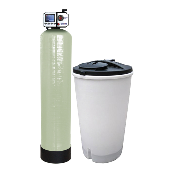
High Flow
Water Softeners
Advertisement
Table of Contents

Related Manuals for Canature 95 Series


Summary of Contents for Canature 95 Series
- Page 1 High Flow Water Softeners 1. Read all instructions carefully before operation. 2. Avoid pinched o-rings during installation by applying (provided with install kit) NSF certified lubricant to all seals. 3. This system is not intended for treating water that is microbiologically unsafe or of unknown quality without adequate disinfection before or after the system.
-
Page 2: Safety Guide
Table of Contents PAGE Safety Guide Proper Installation Unpacking / Inspection Specification Before Starting Installation General Installation Installation Instructions Start Up Instructions Programming About The System Maintenance Main Repair Parts Powerhead Assembly Control Valve Body Assembly Trouble Shooting Safety Guide For your safety, the information in this manual must be followed to minimize the risk of electric shock, property damage or personal injury. -
Page 3: Proper Installation
Proper Installation This water softening system must be properly installed and located in accordance with the Installation Instructions before it is used. Install or store where it will not be ex- 125 psi. If daytime pressure is over 80 posed to temperatures below freezing or psi, night time pressure may exceed the exposed to any type of weather. -
Page 4: Specifications
17.0 gpm Maximum Efficiency 5000 Grains Per Lb Salt Plumbing Connections 1", 1.25", 1.5" Resin Type Canature 8% High Capacity Ion Exchange Resin Electrical Requirements 220 - 12V 50Hz Water Temperature Min 39 - Max. 100 degrees Fahrenheit Water Pressure Min. -
Page 5: Before Starting Installation
Before Starting Installation Tools, Pipe, and Fittings, Other Materials Pliers Some codes may also allow PVC plastic Screwdriver pipe. Teflon tape ALWAYS install the included bypass valve, Razor knife or 3 shut-off valves. Bypass valves let you ... -
Page 6: General Installation
General Installation Typical Softener Location You must first decide how to run in and out pipes to the softener. Look at the house main water pipe at the point where you will connect the softener. Is the pipe soldered copper, glued plastic, PEX, or threaded brass/galvanized? What is the pipe size? Now look at the typical installation illustrations below. -
Page 7: Installation Instructions
Installation Instructions 1. If your hot water tank is electric, turn off the power to it to avoid damage to the element in the tank. 2. If you have a private well, turn the power off to the pump and then shut off the main wa- ter shut off valve. -
Page 8: Softener Installation
Softener Installation... -
Page 9: System Start-Up
System Start-Up Start-up Instructions 1. Plug the valve into an approved power source. 2. When power is supplied to the control, the screen will display “Advancing to Service Wait Please” while it finds the service position. 3. If screen is locked, press MENU for 3 seconds to unlock. Press and hold the SET / REGEN button for 3 seconds to enter the manual regeneration screen. -
Page 10: Main Display
Change Setting Procedure 1. Press the MENU button to enter and exit the menu. 2. Press the UP or DOWN button to select the parameter. 3. Press the SET/REGEN button to enter or activate the parameter for editing. 4. Press the UP or DOWN button to change the value. 5. - Page 11 The screen will be locked after 3 minutes. To unlock the screen press and hold the MENU key for 3 seconds. MANUAL REGENERATION Press and hold the SET REGEN button for 3 seconds to enter the manual regeneration page. The screen will display: 1.
- Page 12 When the valve reaches the Back Wash position. The screen will display: When Back Wash remaining time reaches zero or any button is pressed, the valve will ad- vance to the next position. The screen will display: When the valve reaches the Brine position. The screen will display: When Brining remaining time reaches zero or any button is pressed, the valve will advance to the Rinse position and then the Refill position just like the examples above.
-
Page 13: Main Program
Main Program Press the MENU key to view the main page. 1. Press the MENU button to enter and exit the menu. 2. Press the UP or DOWN button to select the parameter. 3. Press the SET/REGEN button to enter or activate the parameter for editing. 4. - Page 14 Choose Water Hardness & People to adjust the Water hardness and People. The Water Hardness value is the maximum compensated water hardness of the water supply. If Fer- rous Iron is present, add 4 gpg for every 1 ppm Ferrous Iron. The People setting is the number of people living in the home and is used to determine the reserve capacity.
- Page 15 Automatic Calculate mode contains advanced system settings. In Regen Mode you can select four different regeneration modes. The system should be set to Meter Delayed for proper operation. Calendar Clock: the unit will initiate regeneration at the next pre-set regeneration time based on the interval of days between regeneration days.
- Page 16 Choose Regen Time to adjust the time of day for a regeneration to occur. Choose Data Entry to enter the Resin Volume, Salt Amount, and Refill Flow Rate, Unit Ca- pacity, and Reserve Capacity. If your system is assembled from the factory, it has already been programmed with the proper settings.
- Page 17 Restore Defaults will erase all the current settings. Be careful when choosing this since you will lose all the current settings and the default settings loaded back in may not be the cor- rect settings for your system. System Information will provide diagnostic information about your system. Hold the SET/ REGEN button for 3 seconds to reset values to zero.
-
Page 18: About The System
About The System Control Operation During A Power Failure In the event of a power failure, the valve will keep track of the time and day for 48 hours. The programmed settings are stored in a non-volatile memory and will not be lost during a power failure. -
Page 19: System Configuration
System Configuration 95HF System Configuration Brine Line Flow Drain Line Flow Tank Size (Diameter) Injector Set Control (BLFC) Control (DLFC) 12" #4S Black #2S (3.5 GPM) 13" #4S Black #3S (4.5 GPM) 14" #4S Black 0.9 GPM #4S (5.0 GPM) 16"... - Page 20 Removing Power Head Assembly Manually remove the Power Head Assembly: Press and hold Manual Button With 8 hex key, insert Cam Hole, turn the Cam anti-clockwise to the marked position Remove the Connector Remove the Locking Bar ...
- Page 21 Replace Drain Line Flow Control (DLFC) Drain Elbow To replace the Drain Line Flow Control (DLFC): Remove the Clip Pull the Drain Elbow outward Pull the DLFC Holder outward from the Drain Elbow Replace the DLFC Replace Brine Line Flow Control (BLFC) Brine Elbow...
- Page 22 Replace or Cleaning Injectors Sediment, salt and silt will restrict or clog the injector. A clean water supply and pure salt will prevent this from happening. The injector assembly is located on the right side of the control valve. This assembly is easy to clean.
- Page 23 Main Repair Parts Exploded View Main Repair Parts List REPLACEMENT PARTS - TWIN TANK Replacement Part Number Part Description DWG # Quantity 60010052 POWER TRANSFORMER 120V-12V 10010053 95 SOFTENER VALVE 25030001 1465 TANK (250,300) 25030002 1665 TANK (400) 50040006 DISTRIBUTOR KIT 14" - 16" 60010005 OVER FLOW FITTING ASSEMBLY 55010004...
- Page 24 Power Head Exploded View I t e m N o . P a r t N o . P a r t D e s c r i p t i o n Q u a n t i t y 05040038 Bnt95 Cable Jaket(without hole) 26010028...
-
Page 25: Control Valve Exploded View
I t e m N o . P a r t N o . P a r t D e s c r i p t i o n Q u a n t i t y 05040047 Bnt95 Motor (AC12V,2RPM) 05040046 Bnt95 Gear Spring 05040040... -
Page 26: Control Valve Parts List
Control Valve Parts List Item No. Part No. Part Description Quantity 05040025 Bnt95 Piston Rod 05040033 Bnt95 Piston Rod Bush 05040029 Bnt95 Quad Ring Holder 05040004 Bnt95 End Plug Retainer 05040024 Bnt95 Piston Rod Holder 05040022 Bnt95 Spacer Seal 05040002 Bnt95 Valve Boby 05040049 Bnt95 Nut M6... - Page 27 Item No. Part No. Part Description Quantity 05040112 Bnt95 Nozzle-4S 05040113 Bnt95 Nozzle-5S 05040059 Bnt95 Nozzle-3 05040061 Bnt95 Nozzle-4 05040063 Bnt95 Nozzle-5 05040065 Bnt95 Nozzle-6 05040117 Bnt95 Throat-4S 05040118 Bnt95 Throat-5S 05040060 Bnt95 Throat-3 05040062 Bnt95 Throat-4 05040064 Bnt95 Throat-5 05040066 Bnt95 Throat-6 05040099...
-
Page 28: Troubleshooting
Trouble Shooting Issue Possible Cause Possible Solution A. Unit fails to initiate a 1. No power supply. Check electrical service, fuse, etc. regeneration cycle. 2. Defective circuit board. Replace faulty parts. 3. Power failure. Reset time of day. 4. Defective meter. Replace turbine meter.
Need help?
Do you have a question about the 95 Series and is the answer not in the manual?
Questions and answers
I pushed in the red Manuel button. How do I reset it
The manual does not provide specific instructions for resetting the Canature 95 Series after pushing the red manual button. However, to initiate a manual regeneration, you need to press and hold the SET/REGEN button for 3 seconds. If you need to exit or adjust settings, you can follow the Change Setting Procedure:
1. Press the MENU button to enter the menu.
2. Use the UP or DOWN buttons to navigate.
3. Press SET/REGEN to select or save changes.
4. Exit by pressing the MENU button again.
If the system does not reset automatically, you may need to power cycle it by turning it off and back on.
This answer is automatically generated