Table of Contents
Advertisement
FOLLOWTHE INSTALLATION INSTRUCTIONS CAREFULLY. FAILURE TO
INSTALL THE UNIT PROPERLY VOIDS THE WARRANTY. BEFORE YOU
BEGIN INSTALLATION, READ THIS ENTIRE MANUAL. THEN, OBTAIN ALL
THE MATERIALS AND TOOLS
1. Avoid pinched o-rings during installation by applying (provided with install kit) NSF certified
lubricant to all seals.
2. This system is not intended for treating water that is microbiologically unsafe or of unknown
quality without adequate disinfection before or after the system.
REVISION #
2
REVISION DATE September 12, 2013
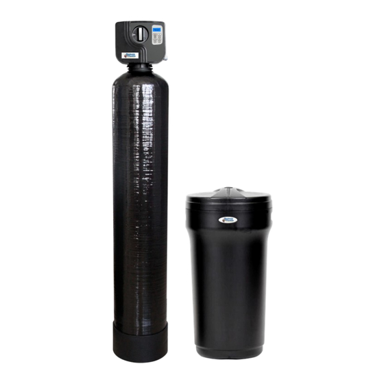
WS665
Water Softener
Advertisement
Table of Contents

Related Manuals for Canature WS665


Summary of Contents for Canature WS665
- Page 1 WS665 Water Softener FOLLOWTHE INSTALLATION INSTRUCTIONS CAREFULLY. FAILURE TO INSTALL THE UNIT PROPERLY VOIDS THE WARRANTY. BEFORE YOU BEGIN INSTALLATION, READ THIS ENTIRE MANUAL. THEN, OBTAIN ALL THE MATERIALS AND TOOLS 1. Avoid pinched o-rings during installation by applying (provided with install kit) NSF certified lubricant to all seals.
-
Page 2: Unpacking Inspection
Table of Contents PAGE Unpacking / Inspection Safety Guide Proper Installation Specification Before Starting Installation Installation Instructions System Start Up Programming Instructions About The System Maintenance Sanitizing Procedure Main Repair Parts Trouble Shooting Warranty Unpacking / Inspection Be sure to check the entire softener for any shipping damage or parts loss. Also note dam- age to the shipping cartons. -
Page 3: Proper Installation
Proper Installation This water softening system must be properly installed and located in accordance with the Installation Instructions before it is used. Do not install or store where it will be maximum. Use a pressure reducing valve exposed to temperatures below freezing or to reduce the pressure. -
Page 4: Specifications
Specifications Water Temperature = Min 39°F / Max 100°F At the stated service flow rates, the pressure drop through these devices will not exceed 15 psig. Operating Pressure = Min 35 PSI / Max 125 PSI ... -
Page 5: Where To Install The Softener
Where To Install The Softener Place the softener as close as possible to The manufacturer will not repair or pay for the pressure tank (well system) or water water damage. meter (city water). A 120 volt electric outlet, to plug the in- ... -
Page 6: Installation Instructions
Installation Instructions 1. If your hot water tank is electric, turn off the power to it to avoid damage to the element in the tank. 2. If you have a private well, turn the power off to the pump and then shut off the main wa- ter shut off valve. - Page 7 Installation Twin Tank...
-
Page 8: Key Pad Configuration
5. Press any button to advance to the RINSE 2. When power is supplied to the control, the position. Check the drain line flow. Allow screen will display “CANATURE” while it the water to run for 3-4 minutes or until finds the service position. -
Page 9: Programming Instructions
Programming Instructions Press SETTINGS to enter programming. If the system has been inactive, you may have to hold and press SETTINGS to unlock the display screen. Press UP or DOWN to select which setting to modify. To adjust a value, MANUAL REGEN. When the display flashes, the value may be changed. -
Page 10: About The System
About The System Operation During A Power Failure In the event of a power failure, the valve will keep track of the time and day for 48 hours. The programmed settings are stored in a non-volatile memory and will not be lost during a power failure. -
Page 11: System Configuration
Automatic Hard Water Bypass During Regeneration The regeneration cycle can last 30 to 180 minutes, after which soft water service will be re- stored. During regeneration, hard water is automatically bypassed for use in the household. Hot water should be used as little as possible during this time to prevent hard water from filling the water heater. -
Page 12: Manual Bypass
Manual Bypass In the case of emergency, such as an overflowing brine tank, you can isolate your water softener from the water supply using the bypass valve located at the back of the control. In normal operation the bypass is open with the on/off knobs in line with the inlet and outlet pipes. - Page 13 Cleaning or Replacing Injectors Sediment, salt and silt will restrict or clog the injector. A clean water supply and pure salt will prevent this from happening. The injector assembly is located on the right side of the control valve. This assembly is easy to clean.
- Page 14 Replacing Brine Line Flow Control (BLFC) TIP: Markings on the BLFC washer should face the direction as shown here. 1. Remove the red clip that secures the brine elbow. 2. Remove the BLFC holder from the elbow fitting. 3. Split the BLFC holder apart and remove the flow washer. 4.
-
Page 15: Care Of Your System
Care of Your System To retain the attractive appearance of your new water softener, clean occasionally with mild soap solution. Do not use abrasive cleaners, ammonia or solvents. Never subject your sof- tener to freezing or to temperatures above 100°F. Resin Cleaner An approved resin cleaner must be used on a regular basis if your water supply contains iron. - Page 16 Main Repair Parts - Connectors REPLACEMENT PARTS - CONNECTORS Replacement Part Number Part Description DWG # Quantity 60010020 3/4" NPT ELBOW 60010019 1" NPT STRAIGHT 60010023 3/4" NPT STRAIGHT 60010079 VALVE COUPLING INLET 60010101 VALVE COUPLING OUTLET (METER SIDE) 60010025 PLASTIC SECURE CLIP 60010046 BYPASS SS CLIP...
-
Page 17: Control Valve Exploded View
Control Valve Exploded View... -
Page 18: Control Valve Parts List
Control Valve Parts List Item No. Part No. Part Discription Quantity 05056087 Screw-M5×12(Hexagon) 05056088 Screw-M5×16(Hexagon with Washer) 05056047 End Plug Retainer 05010081 Bnt65 Piston Rod 05056097 Piston Pin 05056023 End Plug 05056070 Quad Ring 05056024 End Plug Washer 05056022 Piston Retainer 05056181 Piston (Electrical) 05056104... - Page 19 Power Head Exploded View...
-
Page 20: Power Head Parts List
Power Head Parts List Item No. Part No. Part Description Quantity 5056136 Screw-ST3.5×13(Hexagon with Washer) 5056014 Bnt65 Back Cover 5010045 Piston Stem Holder 13000426 Screw-ST2.9×13(Large Wafer) 5056139 Washer-3x13 5056005 Main Gear 5056083 Screw-M4x14 5056166 Screw-ST4.2×12(Large Wafer) 5056141 Washer-4x12 13111004 Washer-4x9 5056016 Refill Regulator 5056015... -
Page 21: Troubleshooting
Trouble Shooting Issue Possible Cause Possible Solution A. Unit fails to initiate a 1. No power supply. Check electrical service, fuse, etc. regeneration cycle. 2. Defective circuit board. Replace faulty parts. 3. Power failure. Reset time of day. 4. Defective meter. Replace turbine meter. -
Page 22: Five Year Limited Warranty
Five Year Limited Warranty Canature USA Inc. will replace the salt tank or cabinet tank, the fibreglass mineral tank, the ion exchange resin, and valve parts provided the failure is due to a defect in material or workmanship and not the result of damage from any of the conditions described in the gen- eral conditions of this warranty.
Need help?
Do you have a question about the WS665 and is the answer not in the manual?
Questions and answers