Table of Contents
Advertisement
785 Automatic Water Filters
1. Read all instructions carefully before operation.
2. Avoid pinched o-rings during installation by applying (provided with install kit) NSF certified
lubricant to all seals.
3. This system is not intended for treating water that is microbiologically unsafe or of unknown
quality without adequate disinfection before or after the system.
REVISION #
2
REVISION DATE 8/20/2014
#80150313
MultiMedia
Neutralizing
Carbon
Nexsand
Canadian Head Office
655 Park St.
Regina, SK S4N 5N1
Eastern Sales & Distribution
20 Steckle Place, Unit 21
Kitchener ON N2E 2C3
U.S. Head Office
8437 10th Avenue North
Golden Valley, MN 55427
Advertisement
Table of Contents

Related Manuals for Canature 785


Summary of Contents for Canature 785
- Page 1 785 Automatic Water Filters MultiMedia Neutralizing Carbon Nexsand 1. Read all instructions carefully before operation. 2. Avoid pinched o-rings during installation by applying (provided with install kit) NSF certified lubricant to all seals. 3. This system is not intended for treating water that is microbiologically unsafe or of unknown quality without adequate disinfection before or after the system.
-
Page 2: Table Of Contents
Table of Contents PAGE Unpacking / Inspection Safety Guide Proper Installation Specification Before Starting Installation Sizing Requirements Installation Instructions System Start Up About The System Maintenance Main Repair Parts Trouble Shooting Warranty Unpacking / Inspection Be sure to check the entire unit for any shipping damage or parts loss. Also note damage to the shipping cartons. -
Page 3: Proper Installation
Proper Installation This water filter system must be properly installed and located in accordance with the Installation Instructions before it is used. Do not install or store where it will not be sweat-solder connections, as required by exposed to temperatures below freezing or state and federal codes. -
Page 4: Specification
Specifications Specifications 585MM-75 585MM-100 585MM-150 585MM-200 585MM-300 Service Flow Rates Normal 4.0 gpm 5.0 gpm 7.0 gpm 10.0 gpm 12.0 gpm Peak 5.0 gpm 7.0 gpm 10.0 gpm 12.0 gpm 15.0 gpm Micron Rating 1520 micron 1520 micron 1520 micron 1520 micron 1520 micron Backwash Flow Rate... -
Page 5: Before Starting Installation
Taste & Odor Filter (Activated Carbon) Neutralizing Filter Unpleasant tastes and doors caused by chlo- The neutralizing filter contains blended media rine or organic substances, such as decayed which raises the pH of acidic water and neu- vegetation and run off, are absorbed by top tralizes its corrosive characteristics. - Page 6 Where To Install The Filter Place the filter tank as close as possible to ter damage. the pressure tank (well system) or water A 120 volt electric outlet, to plug the in- meter (city water). cluded transformer into, is needed within 6 Place the filter tank as close as possible to feet of the filter.
-
Page 7: Sizing Requirements
Sizing Requirements Water Pressure The water system must have a pump big enough to deliver the recommended backwash rate with a minimum pressure at the inlet of the filter of 30 psi. If the existing system can- not do this, it must be upgraded to do so. Whenever possible, the water system should be adjusted to deliver at least 30 psi for even more satisfactory results. -
Page 8: Installation Instructions
Installation Instructions 1. If your hot water tank is electric, turn off the power to it to avoid damage to the element in the tank. 2. If you have a private well, turn the power off to the pump and then shut off the main wa- ter shut off valve. - Page 9 Filter Installation...
-
Page 10: System Start Up
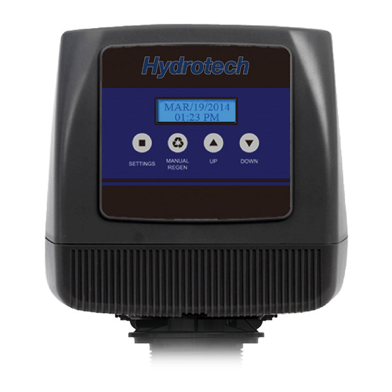
System Start-Up Key Pad Configuration SETTINGS This function is to enter the basic set up infor mation required at the time of installation. MANUAL This function is to initiate an immediate or REGEN delayed manual regeneration. DOWN / Increase or decrease the value of the settings while in the programming mode. - Page 11 Backwash Frequency The table below can be used to help deter- mine the frequency of regeneration for Multi- To prevent bacterial build up in the media, Media and Taste & Odour filters. Use this ta- activated carbon filters should not exceed 6 ble as a guide since individual circumstances days between backwashes.
-
Page 12: About The System
About The System Control Operation During A Power Failure In the event of a power failure, the valve will keep track of the time and day for 48 hours. The programmed settings are stored in a non-volatile memory and will not be lost during a power failure. -
Page 13: System Configuration
New Sounds You may notice new sounds as your filter operates. The regeneration cycle lasts up to 30 minutes. During this time, you may hear water running intermittently to the drain. Automatic Raw Water Bypass During Regeneration The regeneration cycle can last 30 minutes after which filtered water service will be re- stored. -
Page 14: Maintenance
Maintenance Maintenance of your new water filter requires very little time or effort but it is essential. Regular maintenance will ensure many years of efficient and trouble-free operation. 1. Periodically make sure your pump is performing satisfactorily to ensure sufficient water is available for backwashing the filter. - Page 15 Loading the Media Pak Place the distributor tube back down the center of the tank. NOTE: the top of this tube should be plugged with a rag or cork to prevent media from entering. Pour the bag of coarse gravel into the tank, and then pour the bag of fine gravel into the tank. It is important that the distributor tube is not moved or pulled out as it is not possible to put it down to the bottom of the tank once gravel or media are in the tank.
-
Page 16: Main Repair Parts
Replacing Drain Line Flow Control (DLFC) 1. Remove the red clip that secures the drain line elbow. 2. Remove the BLFC washer from the elbow fitting. 3. Reassemble using the reverse procedure. Main Repair Parts... - Page 17 Filter Exploded View Brine tank for softener system only.
- Page 18 Main Repair Parts - Connectors...
-
Page 19: Control Valve Exploded View
Control Valve Exploded View VALVE REPAIR PARTS LIST Replacement Replacement Part Description Part Description Part Number Part Number 60010127 INJECTOR SET #0000 BLACK 60010129 85HE UPFLOW PISTON ASSEMBLY 60010126 INJECTTOR SET #000 GREY 60010171 85HE DOWNFLOW PISTON ASSEMBLY 60010035 INJECTOR SET #00 VIOLET 60010130 85HE SEAL &... -
Page 20: Control Valve Parts List
Control Valve Parts List 785 CONTROL VALVE (DOWNFLOW) Replacement MFG Part Number Part Description DWG # Quantity Part Number 5056087 Screw-M5x12(Hexagon) 5056088 Screw-M5x16(Hexagon With Washer) 5056047 End Plug Retainer 5031016 BNT85HE Piston Rod 5056097 Piston Pin 5031015 BNT85HE Quad Ring Plug Cover... - Page 21 Power Head Exploded View...
-
Page 22: Power Head Parts List
Power Head Parts List 785 POWER HEAD (DOWNFLOW) Replacement MFG Part Number Part Description DWG # Quantity Part Number 5056084 Screw-ST3.5X13 5010037 Screw-ST2.9X10 13000416 Screw-ST3.5X25 5031007 BNT85HE Piston Rod Guide Plate 5056510 Motor-12v/2rpm 5030014 Motor Power Cable 11700005 Wire Connector... -
Page 23: Trouble Shooting
Trouble Shooting... -
Page 24: Warranty
When properly installed and maintained, it will give years of trouble free service. Seven Year Complete Parts Guarantee Canature will replace any part which fails within 84 months from date of manufacture, as indicated by the serial number, provided the failure is due to a defect in material or work- manship.
Need help?
Do you have a question about the 785 and is the answer not in the manual?
Questions and answers