Argo APOLLO Installation Instructions Manual
Air conditioner without outdoor unit
Hide thumbs
Also See for APOLLO:
- Operating instructions manual (22 pages) ,
- Service manual (17 pages) ,
- Manual (16 pages)
Advertisement
Quick Links
Advertisement

Related Manuals for Argo APOLLO


Summary of Contents for Argo APOLLO
- Page 1 INSTALLATION INSTRUCTIONS APOLLO Air conditioner without outdoor unit V 03/20...
- Page 2 CONTENTS 1 - Generalities ......... . .3 2 - Presentation .
-
Page 3: Generalities
For safe installation and trouble-free operation, you must: • Carefully read this instruction booklet before beginning. • Follow each installation or repair step exactly as shown. • Observe all local, state and national electrical (and safety) codes. • Pay close attention to all warning and caution notices given in this manual. •... -
Page 4: Presentation
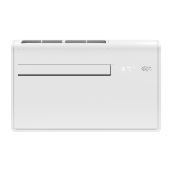
2 - PRESENTATION 2.1 - DESCRIPTION OF THE PARTS 1. Wireless remote control unit 2. Signaling LEDs and receiver 3. Supply air deflector 4. Air intake grille (removable) 5. Air filter 6. Electric cable with plug 7. Air inlet hole with fan 8. - Page 5 2.2 - SIGNALING LEDs 1. Receiver : it receives signals transmitted from the remote control. 2. COOLING LED: This LED lights up when the air conditioner is operating in cooling mode. 3. HEATING LED: This LED lights up when the air conditioner is operating in heating mode.
-
Page 6: Installation
2.4 - DIMENSIONS AND WEIGHT Model Weight (kg) APOLLO Unit: mm 3 - INSTALLATION 3.1 - INSTALLATION SITE SELECTION IMPORTANT NOTES AVOID • The wall must be a perimeter one. • Proximity to heat sources, exhaust fans. • Select a sufficiently strong wall to support the weight of •... - Page 7 Level CAUTION After the selection of the installation site, according Drilling template to the above mentioned points, be sure not to make holes in areas where electrical wiring or conduits are located, damaging them. Make sure that there are no obstacles in the conduits inside the wall affecting the free circulation of the external air.
- Page 8 CAUTION SPECIAL CAUTION WHEN DRILLING AIR HOLES IN THE WALL • Drill the wall using the proper tools in order to facilitate your job and prevent damage. • The best tools for drilling large holes in walls are special drills called core borers with very high twisting torque and adjustable rotating speed depending on the diameter of the hole to be drilled.
- Page 9 - Fix the two external grids as follows: • Apply the adhesive insulating tape (Fig. 7) on the tubes’ wings at the wall. (Fig. 5) Insulating • Fit the small eyelet of the spring, with the long tape stem, on the cap pin (2 caps + 2 springs for each grid).
- Page 10 - Hang up the unit at the anchoring brackets by simultaneously inserting the condensate discharge pipe into the wall hole. Lift it by holding it from the sides of the lower base. To facilitate the operation of fastening it to the bracket, tilt it slightly towards you.
-
Page 11: Electrical Wiring Diagrams
4 - ELECTRICAL WIRING DIAGRAM Colour of the wires Black Brown Blue Green White Yellow... - Page 12 Via Alfeno Varo, 35 - 25020 Alfianello - BS - Italy Tel. +39 0331 755111 - Fax +39 0331 755501 www.argoclima.com...
Need help?
Do you have a question about the APOLLO and is the answer not in the manual?
Questions and answers