Table of Contents
Advertisement
Quick Links
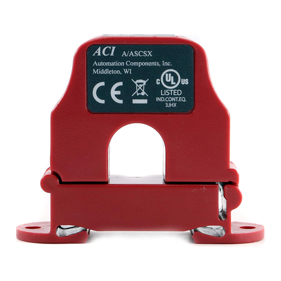
ACI
Automation Components, Inc.
Safety
This product is not intended to be used for Life or Safety applications.
!
This product is not intended for use in any hazardous or classified locations.
Disconnect and lock out all power sources before installation as severe injury or death may result from electrical
shock due to contact with high voltage wires.
Installation
Make sure that all installations are in compliance with all national and local electrical codes. Only qualified individuals that are
familiar with codes, standards, and proper safety procedures for high-voltage installations should attempt installation. The current
switches will not require external power, since the power for the current switch is induced from the conductor being monitored.
Warning: Never rely on the LEDs to determine whether power is present at the current switch. The Red LED will
indicate whether the current is above the adjustable trip point. The Green LED will indicate whether the
current is below the adjustable trip point.
The A/ASCS Series Current Switches should be used on Insulated Conductors Only! The current switch may be mounted in any
position using the (2) #8 x 3/4" Tek screws and the mounting holes in the base or snapped directly on to the 35mm DIN rail (See
Figures 1 & 2 below). Leave a minimum distance of 1" (3 cm) between the current switch and any other magnetic devices such as
contactors and transformers.
Latch Operation:
Pressing down on the two (2) side tabs and swinging the cover open opens the split core current switch as shown in
Figure 3 below. Lifting up on the latch with a flat-tip screwdriver as shown in Figure 4 below can also open the unit. Press down
firmly on the cover to close the current switch. An audible "click" will be heard as the tab slides over the tongue on the base.
Caution: Mating surfaces of the magnetic core are exposed when the sensor is open. Silicone grease, present on the cores to
!
prevent rust, can capture grit and dirt if care is not exercised. Operation can be impaired if anything prevents good
contact between pole pieces. Visually check the mating parts of the core before closing the current sensor.
Please Read Instructions Carefully Before Installation!
3X
Figure 1: Sensor Placed on Rail
Figure 3: Opening Sensor by Hand
2305 Pleasant View Rd. Middleton Industrial Park Middleton, WI 53562
PH: (608) 831-2585 FAX (608) 831-7407
File Name: I0000138 Rev 6.Doc
Installation and Operation Instructions
Part #A/ASCS, A/ASCS-L, A/ASCSX, A/ASCSX-L
3X
Figure 2: Sensor Removed from Rail
Figure 4: Opening w/ Screwdriver
Page 1 of 3
Advertisement
Table of Contents

Related Manuals for aci A/ASCS


Summary of Contents for aci A/ASCS
- Page 1 The A/ASCS Series Current Switches should be used on Insulated Conductors Only! The current switch may be mounted in any position using the (2) #8 x 3/4” Tek screws and the mounting holes in the base or snapped directly on to the 35mm DIN rail (See Figures 1 &...
- Page 2 Wiring ACI recommends the use of a 2 conductor 16 to 22 AWG shielded cable or twisted pair copper wire only for all current switch applications. A maximum wire length of less than 30 meters (98.4 feet) should be used between the A/CS Series current switches and the Building Management System or controller.
- Page 3 200 or 250A trip point position. The adjustable current switch can monitor Under load, Normal Load, and Overload conditions, depending on how it’s set. The procedure below is for the Normal load condition for part numbers A/ASCS & A/ASCS-L. Normal Loads With power on, and the adjustable current switch on the proper range, turn the 15-turn adjustment potentiometer clockwise until the Red LED turns on and stop immediately.
Need help?
Do you have a question about the A/ASCS and is the answer not in the manual?
Questions and answers