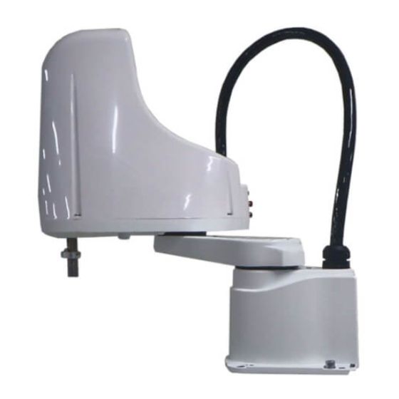
Sign In
Upload
Manuals
Brands
Omron Manuals
Robotics
SCARA R6Y XE Series
Omron SCARA R6Y XE Series Manuals
Manuals and User Guides for Omron SCARA R6Y XE Series. We have
2
Omron SCARA R6Y XE Series manuals available for free PDF download: Installation Manual, Maintenance Manual
Omron SCARA R6Y XE Series Installation Manual (158 pages)
Brand:
Omron
| Category:
Robotics
| Size: 10.31 MB
Table of Contents
Table of Contents
3
Warranty
7
Chapter 1 Introduction
9
Available Manuals
11
Signal Symbols
12
Before Using the Robot (be Sure to Read the Following Notes.)
13
Chapter 2 Functions
17
Robot Manipulator
19
Manipulator Movement
19
Part Names
20
Robot Controller
21
Robot Initialization Number List
22
Chapter 3 Installation
25
Robot Installation Conditions
25
Installation Environments
25
Installation Base
26
Installation
27
Unpacking
27
Checking the Product
28
Moving the Robot R6YXE400
29
Moving the Robot R6YXE610 R6YXE710
30
Installing the Robot
32
Protective Bonding
33
Robot Cable Connection
34
User Wiring and User Tubing
35
Attaching the End Effector
38
Setting the Parameters
38
Relevant Parameters
38
Setting the Parameters According to the Load
38
Confirmation after Setting the Parameters
39
Acceleration Coefficient Vs. Moment of Inertia
40
Parameter Setting According to R-Axis Moment of Inertial of Load
40
R-Axis Tolerable Moment of Inertia and Acceleration Coefficient
40
Equation for Moment of Inertia Calculation
41
Example of Moment of Inertia Calculation
44
Attaching the End Effector
46
Gripping Force of End Effector
48
Limiting the Movement Range with X-Axis and Y-Axis Mechanical Stoppers
49
Installing the X-Axis/Y-Axis Additional Mechanical Stoppers R6YXE400
51
R6Yxe610 R6Yxe710
54
Robot Overrun During Impacts with X-Axis or Y-Axis Mechanical Stopper
54
Limiting the Movement Range with Z-Axis Mechanical Stopper R6YXE610 R6YXE710
55
Installing the Minus Direction Stopper
57
Installing the Plus Direction Stopper
59
Overrun Amounts During Impacts with Z-Axis Additional Mechanical Stopper
60
11. Working Envelope
61
11.2 Performance Area
63
Stopping Time and Stopping Distance at Emergency Stop R6YXE400
64
Stopping Time and Stopping Distance at Emergency Stop R6YXE610
67
Stopping Time and Stopping Distance at Emergency Stop R6YXE710
69
15. Installing the User Wiring and Tubing Newly
71
16. Detaching or Attaching the Covers
72
Extension Shaft Mounting ( for User Wiring/Tubing through Spline Type )
74
18. Tool Flange Mounting
75
R6Yxe610 R6Yxe710
75
19. Permissible Spline Load
77
Over View
81
Overview
81
Adjusting the Origin
82
Return-To-Origin Method
82
Stroke End Method R6YXE400
83
Mark Method R6YXE400
84
Sensor Method (X-Axis, Y-Axis)
84
Machine Reference
85
Return-To-Origin Procedures
86
Stroke End Method R6YXE400
86
Sensor Method (X-Axis, Y-Axis)
87
Adjusting the Machine Reference Value
89
Stroke End Method R6YXE400
89
Mark Method R6YXE400
93
Absolute Reset in Servo on State (Re-Reset)
94
Absolute Reset in Servo off State (Re-Reset)
96
Absolute Reset in Servo on State (New Reset)
99
Absolute Reset in Servo off State (New Reset)
101
Sensor Method (X-Axis, Y-Axis)
103
Changing the Origin Position of X/Y-Axis R6YXE610 R6YXE710
107
Setting the Soft Limits
110
Setting the X-Axis and Y-Axis Soft Limits
110
Relation between the X, Y, and R-Axis Movement Angle, the Z-Axis Movement Distance and the Number of Pulses
111
Setting the R-Axis Soft Limits
111
Setting the Z-Axis Soft Limits
111
Setting the Standard Coordinates
112
Standard Coordinate Setting Using a Standard Coordinate Setup Jig R6YXE400
113
Standard Coordinate Setting Using a Standard Coordinate Setup Jig R6YXE610 R6YXE710
114
Affixing the Stickers for Origin Positions, Movement Directions, and Axis Names
117
Chapter 4 Robot Settings
79
Chapter 5 Periodic Inspection
119
Overview
121
List of Inspection Items
122
Chapter 6 Harmonic Drive Replacement Period
127
Overview
127
Replacement Period
128
Chapter 7 Increasing the Robot Operating Speed
131
Increasing Speed by Arch Motion
131
Increasing the Speed with the WEIGHT Statement
133
Increasing the Speed by the Tolerance Parameter
134
Increasing the Speed by the out Effective Position Parameter
135
Chapter 8 Torque Limit Designated Z-Axis Pushing Action
143
Chapter 9 Specifications
143
Manipulator
143
Basic Specification
143
Regarding the Noise Level
143
External View and Dimensions
144
Robot Inner Wiring Diagram
150
Wiring Table
152
Advertisement
Omron SCARA R6Y XE Series Maintenance Manual (144 pages)
Brand:
Omron
| Category:
Robotics
| Size: 15.8 MB
Table of Contents
Warranty
7
Table of Contents
3
Chapter 1 Introduction
9
Available Manuals
11
Signal Symbols
12
Before Using the Robot (be Sure to Read the Following Notes.)
13
Chapter 2 Attaching, Detaching, and Replacing the Cover
17
Attaching, Detaching, and Replacing the Cover
17
Chapter 3 Periodic Inspection
19
Over View
21
Overview
21
Daily Inspection
22
Six-Month Inspection
23
Applying the Grease
26
Applying the Grease to the Spline Shaft
26
Applying the Grease to the Ball Screw
27
Chapter 4 Adjusting the Origin
31
Adjusting the Machine Reference Value
31
Stroke End Method
31
Changing the X-Axis Reference Value R6YXE400
32
Changing the Y-Axis Reference Value R6YXE400
32
Changing the Z-Axis and R-Axis Reference Values
33
Sensor Method (X-Axis, Y-Axis)
36
Adjusting the X-Axis Machine Reference
36
Adjusting the Y-Axis Machine Reference
38
Mark Method R6YXE400
40
Absolute Reset in Servo on State (Re-Reset)
40
Absolute Reset in Servo off State (Re-Reset)
42
Absolute Reset in Servo on State (New Reset)
45
Absolute Reset in Servo off State (New Reset)
47
Chapter 5 Replacing the Harmonic Drive
49
Cautions on Replacement of the Harmonic Drive
51
Replacement Procedure for Harmonic Drive R6YXE400
52
Replacing the X-Axis Harmonic Drive
52
Preparation
52
Removal
53
Replacement and Reassembly
56
Aging
60
Replacing the Y-Axis Harmonic Drive
61
Preparation
61
Removal
62
Replacement and Reassembly
64
Aging
69
Replacement Procedure for Harmonic Drive R6YXE610 R6YXE710
70
Replacing the X-Axis Harmonic Drive
70
Preparation
70
Removal
71
Replacement and Reassembly
74
Aging
79
Replacing the Y-Axis Harmonic Drive
80
Preparation
80
Removal
81
Replacement and Reassembly
84
Aging
89
Chapter 6 Replacing the Machine Harness
91
Replacing the Machine Harness R6YXE400
93
Removal
94
Assembly
97
Replacing the Machine Harness R6YXE610 R6YXE710
98
Removal
98
Assembly
102
Chapter 7 Motor Replacement
105
X-Axis Motor Replacement
105
Y-Axis Motor Replacement
106
Replacing the Z-Axis Drive Unit R6YXE400
111
Chapter 8 Replacing the Z-Axis Drive Unit
111
Replacing the Z-Axis Motor
112
Replacing the Z-Axis Belt
113
Replacing the Z-Axis Ball Screw
114
Replacing the Z-Axis Brake
115
Replacing the Z-Axis Drive Unit R6YXE610 R6YXE710
117
Replacing the Z-Axis Motor
118
Replacing the Z-Axis Belt
119
Replacing the Z-Axis Ball Screw
120
Replacing the Z-Axis Brake
121
Advertisement
Related Products
Omron SCARA R6YXE400
Omron SCARA R6YXE610
Omron SCARA R6YXE710
Omron R6YXGS800
Omron R6Y XGP Series
Omron R6YXGHP600
Omron R6YXGS900
Omron R6YXG1000
Omron R6YXG700
Omron R6YXG800
Omron Categories
Blood Pressure Monitor
Controller
Accessories
Switch
Inverter
More Omron Manuals
Login
Sign In
OR
Sign in with Facebook
Sign in with Google
Upload manual
Upload from disk
Upload from URL