Table of Contents
Advertisement
Quick Links
Advertisement
Table of Contents

Related Manuals for TLV COSPECT M-COS-3


Summary of Contents for TLV COSPECT M-COS-3
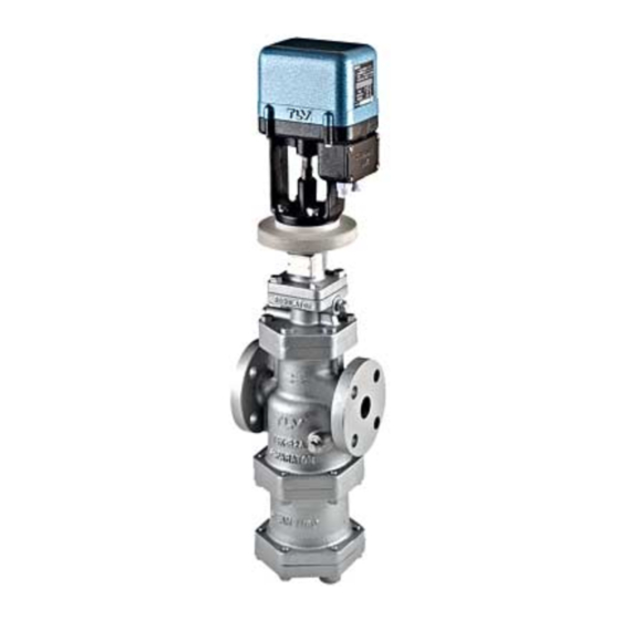
- Page 1 172-65188M-08 (M-COS 3,16,21 Pressure Reducing Valve) 24 June 2015 ISO 9001/ ISO 14001 Manufacturer Kakogawa, Japan is approved by LRQA LTD. to ISO 9001/14001 Motorized Pressure Reducing Valve for Steam COSPECT M-COS-3 / M-COS-16 / M-COS-21 Copyright © 2015 by TLV CO., LTD. All rights reserved...
-
Page 2: Table Of Contents
Contents Introduction ................ 1 Safety Considerations ............2 Specifications ..............4 Acceptable Operating Range ..........6 Correct Usage of the M-COS Motorized Pressure Reducing Valve ..............7 Configuration ..............9 Installation ................ 11 Controller Operation ............18 Maintenance ..............21 Disassembly .............. -
Page 3: Safety Considerations
• The three types of cautionary items above are very important for safety: be sure to observe all of them as they relate to installation, use, maintenance, and repair. Furthermore, TLV accepts no responsibility for any accidents or damage occurring as a result of failure to observe these precautions. - Page 4 Take measures to prevent people from coming into direct CAUTION contact with product outlets. Failure to do so may result in burns or other injury from the discharge of fluids. When disassembling or removing the product, wait until the internal pressure equals atmospheric pressure and the surface of the product has cooled to room temperature.
-
Page 5: Specifications
Specifications Install properly and DO NOT use this product outside the recommended operating pressure, temperature and other specification ranges. CAUTION Improper use may result in such hazards as damage to the product or malfunctions which may lead to serious accidents. Local regulations may restrict the use of this product to below the conditions quoted. - Page 6 Controller Model MC-2 Pressure Display Function (select between displays of measured pressure and upper pressure) Pressure Upper Limit Setting Setting is possible Function Power Source Voltage 100/110 VAC±10% or 200/220 VAC±10% (50/60 H While motor is 7 VA stopped Power Consumption While motor is (TYP.) 65 VA (MAX.) 75 VA...
-
Page 7: Acceptable Operating Range
Acceptable Operating Range M-COS-3 M-COS-16 M-COS-21 Model Primary Pressure Range 0.1 – 0.3 MPaG 0.2 – 1.6 MPaG 1.35 – 2.1 MPaG Within 10 – 84% of the primary pressure Secondary Pressure Minimum adjustable Minimum adjustable Adjustable Pressure pressure of 0.03 MPaG pressure of 0.55 MPaG Range 0.01 –... -
Page 8: Correct Usage Of The M-Cos Motorized Pressure Reducing Valve
Correct Usage of the M-COS Motorized Pressure Reducing Valve Install properly and DO NOT use this product outside the recommended operating pressure, temperature and other specification ranges. CAUTION Improper use may result in such hazards as damage to the product or malfunctions which may lead to serious accidents. - Page 9 4. Precautions for the Installation of Additional Fittings Before or After the M-COS In order to ensure stable steam flow, the piping upstream and downstream of the M-COS must be straight runs. If a M-COS is installed either directly before or after an elbow or control valve, unevenness in steam flow may result in chattering and unstable pressure.
-
Page 10: Configuration
Configuration 15 – 50 mm No. Name Main Body Trap Body Trap Cover Separator Float Float Cover Trap Valve Seat Separator Screen Main Valve Seat Main Valve Main Valve Holder Piston Cylinder Pilot Screen Pilot Screen Holder Pilot Body Pilot Valve Pilot Valve Seat Diaphragm Diaphragm Support... - Page 11 65 – 100 mm No. Name Main Body Trap Body Trap Cover Separator Float Float Cover Trap Valve Seat Separator Screen Main Valve Seat Main Valve Main Valve Holder Piston Cylinder Pilot Screen Pilot Screen Holder Pilot Body Pilot Cover Pilot Valve Pilot Valve Seat Diaphragm...
-
Page 12: Installation
Installation Install properly and DO NOT use this product outside the recommended operating pressure, temperature and other specification ranges. CAUTION Improper use may result in such hazards as damage to the product or malfunctions which may lead to serious accidents. Local regulations may restrict the use of this product to below the conditions quoted. - Page 13 4. Spacer Installation If spacing adjustment is necessary to accommodate installation, install a spacer on the outlet flange. The spacer Correct spacer Correct spacer should consist of a spacer, location location gaskets, bolts and nuts. Fit gaskets to both sides of the spacer between the M-COS outlet and the pipe flange.
- Page 14 8. Blowdown Valve (requires optional plug) Remove the 10 mm (3/8 in) plug (optional) In an environment of heavy dirt or scale, or when the and install the steam-using equipment is used only periodically, blowdown valve such as for room heating equipment be sure to use a blowdown valve.
- Page 15 11. Accessories Always install a shut-off valve, pressure gauge and bypass lines at both inlet and outlet. Ball valves, which will not retain condensate, are recommended for inlet and outlet shut-off valves. The bypass pipe should be at least of the size of the inlet (primary side) pipe.
- Page 16 14. External secondary pressure-sensing line (when required) North American Models are factory prepared for external sensing. An external sensing line MUST be installed. DO NOT SUPPLY STEAM until all piping and a 10 mm secondary pressure sensing line with a slightly falling pitch have been properly installed. Install a shutoff valve in the pressure sensing line for maintenance purposes.
- Page 17 All models except North American models are factory prepared for internal sensing. When internal pressure sensing is required for North American models, please contact the nearest TLV representative to request both a connecting tube, which must be installed in place of the blind pin, and a threaded secondary pressure sensing plug.* Follow the connecting tube installation procedure shown below:...
- Page 18 Wiring MC-2 Pressure Power Ground Motor Supply Sensor Red Black White Red White Shield* (–) Class 3 Grounding AC100V AC200V * Wiring for the pressure switch should be made only when necessary. Class 3 Grounding 1. Before arranging wiring, check the correct supply voltage values specified for the controller unit and for the actuator (motor) once again.
-
Page 19: Controller Operation
Controller Operation <MC-2> (5) Pressure Indicator (7) Maximum Allowable Pressure Setting Knob (6) Selector Switch (4) Maximum Allowable Pressure LED (1) Power Supply LED (2) Pressure Setting Lever Switch (1) Power Switch (3) Pressure Lock Switch Part Names and Features NOTE: Pressure values in parentheses ( ) are for the 500 kPa (0.5 MPaG) model. - Page 20 (5) Pressure Indicator LED in the pressure indicator window light up when the power switch (1) is turned ON indicating either the measured pressure or the maximum allowable pressure, depending on the setting on the selector switch (6). Values available for indication are between 000 to 1999 kPa (500 kPa). Pressure indicator shows about -500 (-125) on the measured pressure side when the pressure sensor is not connected.
- Page 21 Operation Procedures 1. Turn ON the power to the controller. (Thereupon, LEDs for power ON and for the pressure indicator are lighted.) Make sure that the pressure lock switch is turned OFF. 2. Set the maximum allowable pressure. With the selector switch set at the maximum allowable pressure side, operate the maximum allowable pressure setting knob to set the desired maximum allowable pressure.
-
Page 22: Maintenance
Maintenance Take measures to prevent people from coming into direct contact with product outlets. Failure to do so may result in burns or other injury from CAUTION the discharge of fluids. Be sure to use only the recommended components when repairing the product, and NEVER attempt to modify the product in any way. -
Page 23: Disassembly
Disassembly NEVER apply direct heat to the float. The float may explode due to increased internal pressure, causing accidents leading to serious injury or WARNING damage to property and equipment. Use hoisting equipment for heavy objects (weighing approximately 20 kg or more). Failure to do so may result in back strain or other injury if CAUTION the object should fall. - Page 24 <Valve> Disassembling the Pilot Section The diaphragm is removed by utilizing the notch in the pilot body. Loosen the pilot valve seat with a box wrench and remove it. Lift the pilot valve spring up and out with a pair of tweezers. Then loosen and remove the pilot screen holder to remove the pilot screen.
- Page 25 Disassembling the Piston Section Remove the pilot body after loosening and removing the bolts. During this process, pay attention not to lose the connecting tubes (2). Remove the piston, cylinder and the silencer (for 65 – 100 mm only) from the main body.
- Page 26 Disassembling the Separator and Main Valve Sections Turn the M-COS upside down for easy dismantling of the separator and main valve. Loosen the bolts and remove the trap body. Be careful, as the separator may drop off when the M-COS is returned to the normal attitude. Removal of the separator and pressed-in sleeve permits removal of the main valve spring, the main valve, the main valve holder and the separator screen.
- Page 27 Disassembling the Steam Trap Section Loosen the bolts and remove the trap cover. Be careful, as hot condensate may splash out. Remove the bolts from the trap cover and the float cover to reveal the float. Remove the float, then loosen the trap valve seat with a box wrench and remove it. →Check to verify that there is no deformation of the float, abnormality in the trap valve seat or dirt accumulation in the trap cover.
- Page 28 <Actuator> Disassembling the Actuator Section By removing hexagon bolts, the actuator section with adjustment screw can be dismantled from the spring housing. An insulation plate is provided between the flanges. Refrain from disassembling any further. →Check to see if the adjustment screw rotates smoothly. Check for seizing, chipping or similar defects on the threaded portion of the adjustment screw.
- Page 29 <Controller> Replacing the Fuse If the power ON LED fails to light even after the power switch is turned ON, check whether the fuse is blown. Controller (Rear View) Circuit Board Fuse Rear Cover Set screws to be removed Figure 5.1 Figure 5.2 CAUTION: Be sure the main power is switched OFF before checking the fuse.
- Page 30 <Pressure Sensor (A standard TLV accessory)> Inspection of Pressure Sensor A periodic inspection should be carried out at least biannually. 1. Check for corrosion or clogging with dirt. Check for corrosion or clogging with dirt, etc., that may have occurred at the pressure inlet to the pressure sensor and the siphon pipe, 2.
- Page 31 Exploded View 60 – 100 mm 60 – 100 mm 15 – 50 mm 15 – 50 mm Actuator (Drive Unit) Actuator (Drive Unit) Actuator (Drive Unit) Actuator (Drive Unit) Adjustment Section Adjustment Section Adjustment Section Adjustment Section Pilot Section Pilot Section Pilot Section Pilot Section...
-
Page 32: Reassembly
Reassembly Assemble the unit using the same procedure as used for disassebling it; but in reverse order. Observe the following precautions: 1. The PTFE gaskets may be re-used if free from fault, crushing or deformation. 2. Apply anti-seize to the threaded portion of screws and bolts, the spring retainer, ball and adjustment screw. -
Page 33: Troubleshooting
Troubleshooting NEVER apply direct heat to the float. The float may explode due to increased internal pressure, causing accidents leading to serious injury or WARNING damage to property and equipment. When disassembling or removing the product, wait until the internal pressure equals atmospheric pressure and the surface of the product CAUTION has cooled to room temperature. - Page 34 Troubleshooting Chart Problem Symptom Cause Remedy The M-COS body is The secondary No steam is being Check the valves pressure does not not warm supplied or the inlet and piping rise valve is closed The body is warm, The entrance to the Clean or blow down but the pressure screens or strainer is...
- Page 35 Troubleshooting Chart (continued) Problem Symptom Cause Remedy Hunting or chattering Chattering never Condensate is Check the trap occurs stops contained, or the trap Check the piping (continued) is blocked The selected model is Check the model inappropriate for the selection, replace the M-COS if service conditions (specifications)
-
Page 36: Product Warranty
One year following product delivery. 2. Warranty Coverage TLV CO., LTD. warrants this product to the original purchaser to be free from defective materials and workmanship. Under this warranty, the product will be repaired or replaced at our option, without charge for parts or labor.
Need help?
Do you have a question about the COSPECT M-COS-3 and is the answer not in the manual?
Questions and answers