Sign In
Upload
Download
Table of Contents
Contents
Add to my manuals
Delete from my manuals
Share
URL of this page:
HTML Link:
Bookmark this page
Add
Manual will be automatically added to "My Manuals"
Print this page
×
Bookmark added
×
Added to my manuals
Manuals
Brands
TLV Manuals
Control Unit
Cospect MC-COS-3
Instruction manual
TLV COSPECT MC-COS-3 Instruction Manual
High-precision multi-control valve for steam, actuator: mc-ga2
Hide thumbs
1
Table Of Contents
2
3
4
5
6
7
8
9
10
11
12
13
14
15
16
17
18
19
20
21
22
23
24
25
26
27
28
29
30
31
32
33
34
35
36
37
page
of
37
Go
/
37
Contents
Table of Contents
Troubleshooting
Bookmarks
Table of Contents
Table of Contents
Contents Introduction
Safety Considerations
Specifications
Correct Usage of the MC-COS Multi-Control Valve
Configuration
Installation
Wiring Instructions
Setting the Valve Coefficient
Operation
Inspection and Maintenance
Disassembly
Reassembly
Troubleshooting
Product Warranty
Advertisement
Quick Links
Download this manual
172-65169MA-08 (MC-COS Multi-control Valve) 28 May 2010
ISO 9001/ ISO 14001
Manufacturer
Kakogawa, Japan
is approved by LRQA LTD. to ISO 9001/14001
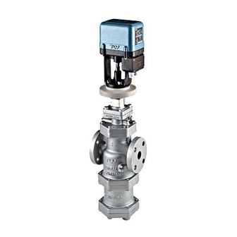
High-precision Multi-control Valve for Steam
COSPECT
MC-COS-3/MC-COS-16
Actuator: MC-GA2
Copyright © 2010 by TLV CO., LTD.
All rights reserved
Table of
Contents
Previous
Page
Next
Page
1
2
3
4
5
Advertisement
Table of Contents
Need help?
Do you have a question about the COSPECT MC-COS-3 and is the answer not in the manual?
Ask a question
Questions and answers
Related Manuals for TLV COSPECT MC-COS-3
Control Unit TLV MC-COSR-3 Instruction Manual
High-precision multi-control valve for steam. actuator: mc-ga2 (38 pages)
Control Unit TLV Cospect MC-COS-16 Instruction Manual
High-precision multi-control valve for steam, actuator: mc-ga2 (37 pages)
Control Unit TLV COSPECT M-COS-3 Instruction Manual
Motorized pressure reducing valve for steam (36 pages)
Control Unit TLV MB12A Instruction Manual
Motorized ball butterfly valve (27 pages)
Control Unit TLV MB12B Instruction Manual
Motorized ball butterfly valve (27 pages)
Control Unit TLV VS1A Instruction Manual
Rapid initial air vent (14 pages)
Control Unit TLV CV10 Instruction Manual
(27 pages)
Control Unit TLV COSR-3 Instruction Manual
Pressure reducing valve for steam (34 pages)
Control Unit TLV SS1VG Instruction Manual
Free float drain trap (2 pages)
Control Unit TLV BE8H Series Instruction Manual
Bellows sealed valve (8 pages)
Control Unit TLV COSPECT PN-COS-16 Instruction Manual
Pneumatic control valve for steam (27 pages)
Control Unit TLV PCV-1 Instruction Manual
Surplussing valve (primary pressure control valve) for steam and steam condensate (16 pages)
Control Unit TLV S-COS-16 Instruction Manual
Pressure reducing valve for steam (28 pages)
Control Unit TLV CK3M Instruction Manual
Disc type check valve (12 pages)
Control Unit TLV PowerDyne QuickTrap P46UC Instruction Manual
Universal thermodynamic steam trap (33 pages)
Control Unit TLV CK3 Series Instruction Manual
Disc type check valves (12 pages)
This manual is also suitable for:
Cospect mc-cos-16
Table of Contents
Print
Rename the bookmark
Delete bookmark?
Delete from my manuals?
Login
Sign In
OR
Sign in with Facebook
Sign in with Google
Upload manual
Upload from disk
Upload from URL


Need help?
Do you have a question about the COSPECT MC-COS-3 and is the answer not in the manual?
Questions and answers