Table of Contents
Advertisement
Quick Links
BEFORE USING THE POWER SUPPLY UNIT
Be sure to read and understand this instruction manual thoroughly before using this product. Pay attention to all cautions and
warnings before using this product. Incorrect usage could lead to an electrical shock, damage to the unit or a fire hazard.
DANGER
Never use this product in locations where flammable gas or ignitable substances are present. There are potential risks of igniting
these substances caused by arcing.
WARNING
Do not touch this product or its internal components while circuit is live, or shortly after shut down. There may be
high voltage or high temperature present and you may receive an electric shock or burn.
While this product is operating, keep your hands and face away from it as you may be injured by an unexpected situation.
Do not make unauthorized changes to this product, otherwise you may receive an electric shock. It will also void the product
warranty.
Do not drop or insert anything into the product. It might lead to a failure, fire or electric shock.
Do not use this product if abnormal conditions such as emission of smoke and/or abnormal smell, etc... are present. It might lead
to fire and/or electric shock. In such cases, please contact TDK-Lambda. Do not attempt to repair by yourself, as it is dangerous
for the user.
Do not operate these products in the presence of condensation. It might lead to fire or electric shock.
CAUTION
This power supply is designed and manufactured for use within an end product such that it is accessible only to trained SERVICE
ENGINEERS.
Confirm that the connections to input/output terminals, and signal terminals are correct as specified in this instruction manual
before turning on the power.
Input voltage, Output current, Output power, ambient temperature, case temperature, and ambient humidity should be kept within
the specifications, otherwise the product may be damaged.
Do not operate or store this product in an environment where condensation can occur. Waterproof treatment or special storage
and handling is necessary.
The equipment has been evaluated for use in a Pollution Degree 2 environment.
Do not use this product in environment with a strong electromagnetic field, corrosive gas or conductive substances.
For applications, which require very high reliability, such as nuclear related equipment, medical equipment, traffic control
equipment, etc., it is necessary to provide a fail-safe mechanism in the end equipment.
Do not inject abnormal voltages into the output terminals or signal terminals of this product. The injection of reverse voltage or
over voltage exceeding nominal output voltage into these terminals can damage the internal components of the product.
Never operate the product under over-current or short circuit conditions. Failure or other damage may occur.
The output voltage of this power supply unit is considered to be a hazardous energy level (The voltage is 2V or more and the
electric power is 240W or more). It must not be made accessible to users. Protection must be provided for Service Engineers
against indirect contact with the output terminals and/or to prevent tools being dropped across them. While working on this product,
the AC input power must be switched off, and the input, output, +VBus, and -VBus terminal voltages should be at a safe level.
The application circuits and their parameters are for reference only. Be sure to verify effectiveness of these circuits and their
parameters before finalizing the circuit design.
Use a Fast-Blow external fuse to each module to ensure safe operation and compliance with the safety standards to which it is
approved. The recommended input fuse rating within the instructions is as follows: 10A, 250V fast acting fuse. The breaking
capacity and voltage rating of this fuse may be subject to the end use application.
REV 2.8 (March 30, 2020)
PFH500 Series
Instruction Manual
TDK-Lambda
PFH500-SERIES
INSTRUCTION MANUAL
1
Advertisement
Table of Contents

Subscribe to Our Youtube Channel
Related Manuals for TDK-Lambda PFH500 Series


Summary of Contents for TDK-Lambda PFH500 Series
-
Page 1: Before Using The Power Supply Unit
Do not use this product if abnormal conditions such as emission of smoke and/or abnormal smell, etc… are present. It might lead to fire and/or electric shock. In such cases, please contact TDK-Lambda. Do not attempt to repair by yourself, as it is dangerous for the user. - Page 2 This information in this document is subject to change without prior notice. Please refer to the latest version of the data sheet, etc., for the most up-to date specifications of the product. No part of this document may be copied or reproduced in any form without prior written consent TDK-Lambda. REV 2.8 (March 30, 2020)
-
Page 3: Table Of Contents
TDK-Lambda PFH500-SERIES INSTRUCTION MANUAL Contents BEFORE USING THE POWER SUPPLY UNIT ....................1 Model Name Identification Scheme......................5 Ordering Table Module Pinout (Pin Side-Up)........................6 Circuit Block Diagram ..........................7 Sequence Timing Diagram .......................... 8 Terminal Connecting Method ........................9 F1 External Input Fuse C1 (1uF);... - Page 4 TDK-Lambda PFH500-SERIES INSTRUCTION MANUAL 6.13 PMBus Communication 6.14 Ripple and Noise 6.15 Series Operation 6.16 Isolation Resistance 6.17 Withstand Voltage Test (Hipot Test) Thermal Considerations and Mounting Method ..................27 Thermal Consideration Output Current / Case Temperature Thermal Derating Recommended Soldering Condition Recommended Washing Condition Troubleshooting Guide..........................
-
Page 5: Model Name Identification Scheme
TDK-Lambda PFH500-SERIES INSTRUCTION MANUAL Model Name Identification Scheme Ordering Table Case Parallel Feature Set Output Mounting Operation (Default) Length (Default) (Default) 0: Thru-Hole 0: No Load Share 12: 12 VDC F: Full Features 1: Threaded D: Droop Load 28: 28 VDC... -
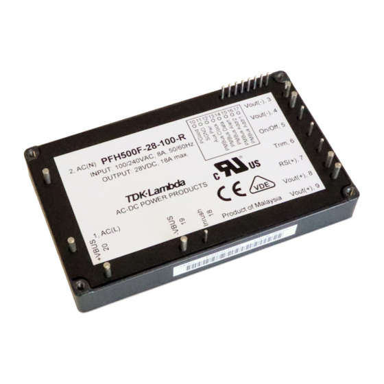
Page 6: Module Pinout (Pin Side-Up)
TDK-Lambda PFH500-SERIES INSTRUCTION MANUAL Module Pinout (Pin Side-Up) PIN # PIN DESIGNATION FUNCTION PIN # PIN DESIGNATION FUNCTION AC (L) AC Input - Live Line SGND Secondary Signal Ground AC (N) AC Input - Neutral Line Aux Pwr Auxiliary Supply Output... -
Page 7: Circuit Block Diagram
TDK-Lambda PFH500-SERIES INSTRUCTION MANUAL Circuit Block Diagram PFC Circuit DC-DC Circuit Vbus DC-DC Inrush Bridgeless Synchro. Fuse Bridge Circuit PFC Conv. Rectifiers Converter Relay Ipeak Vin Detect Sense DC-DC UVP/OVP Vo_sns Digital Digital Controller Controller ON/OFF Digital (OVP/UVP) Trim Iin Detect... -
Page 8: Sequence Timing Diagram
TDK-Lambda PFH500-SERIES INSTRUCTION MANUAL Sequence Timing Diagram NOTE: PFH Series product has a remote ON/OFF pin (PIN# 5) that is referenced to output return. REV 2.8 (March 30, 2020) -
Page 9: Terminal Connecting Method
Terminal Connecting Method In order to use the PFH500 series, this module must be connected with external components according to Figure 5-1. Pay attention to the wiring details. If the PFH module is wired incorrectly, the power module may be damaged. -
Page 10: C1 (1Uf); C4 (1Uf); C5 (2.2Uf) Film Capacitor Or Class X Safety Capacitor
TDK-Lambda Americas recommends the customers to verify the actual ripple current flowing through each X capacitor by measuring the current flow. Connect C5 as close to the input terminals of PFH500 series power module [i.e. AC(L) and AC(N)] as possible. Recommended Voltage Rating of X - Capacitors: 250VAC or greater... -
Page 11: L1 (6.3Mh); L2 (6.3Mh) Common Mode Choke
L1 (6.3mH); L2 (6.3mH) Common Mode Choke Add recommend common mode chokes to reduce EMI noise. When using multiple PFH500 series modules in parallel, it is important to provide EMI filtering (including X caps, Y caps, and common mode chokes) for each PFH500 module. -
Page 12: C11 (470Pf); C12 (470Pf)
TDK-Lambda PFH500-SERIES INSTRUCTION MANUAL Selection Method of External Bulk Capacitor for VBUS C9 & C10 capacitor values are determined by Verification testing should be performed over the entire intermediate bus voltage ripple, ripple current, and operating temperature range. hold-up time. Select a capacitor value such that VBUS voltage ripple does not exceed 15Vp-p. -
Page 13: C15; C16 - Output Electrolytic Capacitors
TDK-Lambda PFH500-SERIES INSTRUCTION MANUAL 5.11 C15; C16 – Output Electrolytic Capacitors Connect C15 and C16 approximately 50mm from the output terminals Vo(+) and Vo(-) of the PFH Series power module to stabilize the module operation. Note that the output noise ripple and the characteristics of the power module during input line turn off might be affected by the ESR and ESL values of the selected electrolytic capacitors. - Page 14 R2 is between 20Ω minimum and 30Ω maximum. A 22Ω ceramic wire wound, thermal fused inrush resistor is typically recommended. Note: PFH500 series module will not operate if this external inrush resistor is not present. Selection Method of External Resistor (1) Calculating Resistance Value for R2: Resistance can be calculated by the formula below.
-
Page 15: Rl Inrush Relay (12V Coil, 10A/277Vac; 16A/125Vac)
Input AC voltage source should be within the ranged from 85 - 265Vrms (47-63Hz). Connecting the PFH Series module to any power source outside of this specified range will prevent the module from starting. PFH500 series power module is certified by various safety agencies with a certified label indicating: 100-240Vac, 50- 60Hz, 8A. - Page 16 TDK-Lambda PFH500-SERIES INSTRUCTION MANUAL The trim-up resistor (Rt_up) values from +5% to +20% , can be found in Tables 6-1. The trim-up circuit connection is shown in Figure 6-2. Trim resistors should have +/-1% or better tolerance. Table 6-1 External Trim-Up Resistor Value for PFH500F –...
-
Page 17: Inrush Current
TDK-Lambda PFH500-SERIES INSTRUCTION MANUAL The trim-down resistor (Rt_down) values for the trim-down voltage range from -5% to -20% can be found in Tables 6-2. The trim down connection diagram is shown in Figure 6-4. Table 6-2 External Trim-Down Resistor Value PFH500F –... -
Page 18: Output Over Voltage Protection (Ovp)
TDK-Lambda PFH500-SERIES INSTRUCTION MANUAL Output Over Voltage Protection (OVP) PFH Series modules are equipped with an OVP protection function. The OVP function activates when output voltage is greater than the OVP trip-point. When the OVP triggers, the module output will shut down either with latch or auto-recovery depending upon the option code specified. -
Page 19: Over Temperature Protection (Otp)
Should a noise filter inductor be inserted between Vo(+) pin(s) and the load terminal, the RS(+) sense must be connected on the module’s side of the inductor. Some precaution in the layout may be needed. Contact TDK-Lambda Technical Support for assistance if needed. Voltage Stable at Load Terminals... -
Page 20: On-Off Control
TDK-Lambda PFH500-SERIES INSTRUCTION MANUAL ON-OFF Control PFH Series modules have an ON-OFF control pin, which is used to enable (turn on) or disable (turn off) the module. When this pin is low, the PFH module is enabled. Internally, this pin is connected to a 10K pull-up resistor that is in series with 3.3V source. -
Page 21: Auxiliary Bias Power
TDK-Lambda PFH500-SERIES INSTRUCTION MANUAL 6.11 Auxiliary Bias Power PFH Series modules have an Auxiliary Bias Supply pin, referenced to Vout(-). This auxiliary bias is internally over-current protected. It is capable of providing a loosely regulated 12V bias (10V ~ 14V, with 200mA maximum current). -
Page 22: Pmbus Communication
PFH Series module operating status and telemetry can be monitored over the PMBus. PMBus can also be used to modify some of the operation parameters and/or limit settings, etc. For details, please refer to TDK-Lambda “PFH PMBus Specification and Application Note”. -
Page 23: Ripple And Noise
TDK-Lambda PFH500-SERIES INSTRUCTION MANUAL 6.14 Ripple and Noise The output ripple and noise is measured in accordance with industry practices. The output noise measurement connection can be found in the diagram shown in Figure 6-9 below. A 0.1µF ceramic capacitor, C13, and four (4) 10µF ceramic capacitors, C14, are connected across the PFH module’s output bus at a location 50mm from the module output terminals. -
Page 24: Series Operation
6.15 Series Operation To increase the output voltage of a PFH Series module, it is possible to connect two or more PFH500 Series modules in series. For two modules connected in series configuration, the connection diagrams are shown in Figure 6-10a and Figure 6- 10b. -
Page 25: Isolation Resistance
TDK-Lambda PFH500-SERIES INSTRUCTION MANUAL 6.16 Isolation Resistance The isolation resistance between the PFH Output and the module’s case typically will be 100M with 500VDC applied. PMBus Interface RS (+) Vo(+) Vo(+) Vo(-) Insulation Resistance Tester Vo(-) Trim AC(L) PFH500F ON/OFF... - Page 26 TDK-Lambda PFH500-SERIES INSTRUCTION MANUAL PMBus Interface PMBus Interface RS (+) RS (+) Vo(+) Vo(+) Vo(+) Vo(+) Vo(-) Vo(-) Vo(-) Vo(-) Trim Trim AC(L) AC(L) PFH500F PFH500F ON/OFF ON/OFF AC(N) AC(N) Hipot Tester Aux Power Aux Power SGND SGND Case Case...
-
Page 27: Thermal Considerations And Mounting Method
For any technical issues related to thermal derating, thermal test set-up, mounting, the heat sink attachment, and use of the thermal interface material, please contact TDK-Lambda Americas for technical support. Case temperature thermal measurement location is shown in Fig. 7-1. -
Page 28: Output Current / Case Temperature Thermal Derating
TDK-Lambda PFH500-SERIES INSTRUCTION MANUAL Output Current / Case Temperature Thermal Derating PFH500F module is derated according to Figure 7-2. Derating varies based on AC input voltage and desired case temperature/output current. Fig. 7-2a PFH500F-28-xxx Derating Curves. Fig. 7-2b PFH500F-12-xxx Derating Curves. -
Page 29: Recommended Soldering Condition
Preheat 130 ºC Recommended Washing Condition After soldering, the following washing condition is recommended. For other washing conditions, consult TDK-Lambda Americas Technical Support. (1) Recommended washing solution IPA (Isopropyl Alcohol) (2) Washing method In order to avoid penetration inside the power module, washing should be done with brush. Then, dry up thoroughly after washing. -
Page 30: Troubleshooting Guide
TDK-Lambda PFH500-SERIES INSTRUCTION MANUAL Troubleshooting Guide To ensure proper operation of the PFH module, the recommended test setup, required external components, connections and specified test limits as described in this Instruction Manual should always be followed. In the unlikely event that the PFH module encounters the abnormal performance behavior described below, the troubleshooting guide maybe able to help rule out any external factors outside of the module that may be causing the abnormality. -
Page 31: Warranty Period
TDK-Lambda PFH500-SERIES INSTRUCTION MANUAL Warranty Period Standard warranty is 3 years or whatever is specified on the purchasing agreement. The following cases are not covered by warranty: (1) Improper use like dropping products, applying excessive shock, spilling fluids on the module, etc.…... -
Page 32: Appendix
TDK-Lambda PFH500-SERIES INSTRUCTION MANUAL 10 Appendix 10.1 EMI Conducted Emissions CISPR 32:2015 Class B Recommended Values Figure 10.1 PFH500F-12-xxx-R C13, C14, C15, C1, C4 1µF Film Capacitor 10µF Ceramic Capacitor 1500µF Electrolytic Capacitor C2, C3 3300pF Ceramic Capacitor C17, C18 2.2µF Film Capacitor... - Page 33 TDK-Lambda PFH500-SERIES INSTRUCTION MANUAL Figure 10.2 PFH500F-28-xxx-R C1, C4 1µF Film Capacitor C17, C18 470µF Electrolytic Capacitor C2, C3 3300pF Ceramic Capacitor 10A, 250V, Fast Blow 2.2µF Film Capacitor L1, L2 6.3mH C6, C7, C11, C12 470pF Ceramic Capacitor R1, R3, R4 470kΩ, 2W...
- Page 34 TDK-Lambda PFH500-SERIES INSTRUCTION MANUAL Figure 10.3 PFH500F-48-xxx-R 2.2µF Film Capacitor 470µF Electrolytic Capacitor C1, C4, C5 C17, C18 C2, C3 3300pF Ceramic Capacitor 10A, 250V, Fast Blow C6, C7 470pF Ceramic Capacitor L1, L2 6.3mH C6A, C7A 330pF Ceramic Capacitor R1, R3, R4 470kΩ, 2W...
- Page 35 No license is granted by implication or otherwise under any patent or patent rights of TDK-Lambda. TDK components are not designed to be used in applications, such as life support systems, wherein failure or malfunction could result in injury or death.
- Page 36 For Additional Information, please visit https://product.tdk.com/info/en/products/power/index.html...
Need help?
Do you have a question about the PFH500 Series and is the answer not in the manual?
Questions and answers