DeFelsko PosiTector UTG Full Manual
Ultrasonic thickness gage
Hide thumbs
Also See for PosiTector UTG:
- Instruction manual (77 pages) ,
- Quick manual (71 pages) ,
- Manual (49 pages)

Subscribe to Our Youtube Channel
Related Manuals for DeFelsko PosiTector UTG


Summary of Contents for DeFelsko PosiTector UTG
- Page 1 Ultrasonic Thickness Gage Full Guide v. 3.3 Advanced model 1.800.561.8187 information@itm.com www. .com...
-
Page 2: Table Of Contents
Table of Contents Table of Contents Introduction ............Quick Start ............Certification ............Probes ..............How to Measure ..........Surface Conditions ..........Calibration, Verification and Adjustment ..... Menu Operation ..........Cal Settings Menu ..........10 Zero ..............10 Thickness ............11 Material ............ - Page 3 Accessing Stored Measurement Data ....26 PosiSoft Desktop ........... 26 PosiSoft.net ........... 26 PosiTector App ..........Connect Menu ............. 26 WiFi..............26 Access Point........... 27 USB..............28 USB Serial Streaming........29 Sync.net Now..........29 Bluetooth Smart..........30 Bluetooth............
-
Page 4: Introduction
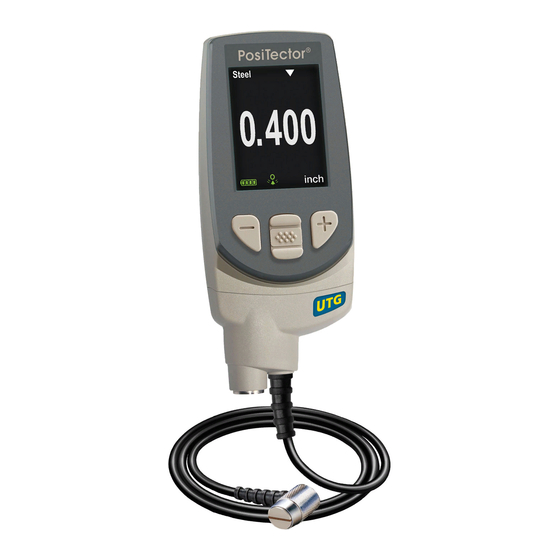
5. Measure the part (see pg. 6) Protective Cap PosiTector UTG gages ship with a protective plastic cap over the probe. Remove this cap prior to use. Replace it when the instrument is not in use to protect the probe. - Page 5 Wrist Strap DeFelsko recommends attaching and wearing the supplied wrist strap. Protective Lens Shield The LCD is covered with a thin plastic film for protection against fingerprints and other marks during shipment. This film, while usually removed before using the instrument, can be left in place to protect against paint overspray or debris.
-
Page 6: Certification
Unit of Measurement inch Icon Certification All PosiTector UTG probes include a Certificate of Calibration. For organizations with re-certification requirements, instruments may be returned at regular intervals for calibration. DeFelsko recommends that customers establish calibration intervals based upon their own experience and work environment. - Page 7 PosiTector UTG probes are available for a variety of wall thickness applications: • PosiTector UTG CA / UTG C – dual element, single-echo probe ideal for measuring severely corroded/eroded materials. PosiTector UTG CA models feature a built-in probe, while PosiTector UTG C models feature a probe mounted on a 1m (3ft) cable.
- Page 8 Thus the single-echo technique will produce a thickness result greater than the actual combined coating metal thickness. The PosiTector UTG M and UTG P in multiple-echo mode determine thickness by measuring the time between at least three consecutive back wall echoes.
-
Page 9: How To Measure
The resultant thickness calculation made by the instrument is therefore an accurate measurement of the steel thickness only, disregarding the coating thickness. PosiTector UTG P (Precision) probes automatically switch between multiple echo and single echo operation depending upon the type and thickness of the material being measured. -
Page 10: Surface Conditions
When using the PosiTector UTG P, it is especially important to avoid using excess couplant when taking a reading. The PosiTector UTG P is designed for measuring thin materials and will measure a thin layer of couplant left on the probe face after a measurement. -
Page 11: Calibration, Verification And Adjustment
NOTE: On smooth, uncoated metal surfaces PosiTector UTG M and UTG P probes (in multiple-echo mode) may occasionally be unable to give a measurement result even when the "coupled" symbol appears. Use additional couplant and lighter pressure on the probe when measuring. -
Page 12: Menu Operation
Menu Operation Gage functions are menu controlled. To access the Menu, power-up the Gage, then press the center navigation button. Below is a sample menu for a PosiTector UTG Advanced Model: Memory Statistics Some buttons have a tick box to their Cal Settings right to indicate current status. -
Page 13: Cal Settings Menu
(Center/Select) Cal Settings Menu Zero PosiTector UTG probes must be “zeroed” after a reset and periodically during use. The Zero process compensates for probe wear and temperature. To maintain the best accuracy, perform a Zero when the ambient temperature changes. -
Page 14: Thickness
Calibration Adjustment The PosiTector UTG is factory calibrated. In order for it to take accurate thickness measurements of a particular material it must be set to the correct sound velocity for that material. Be aware that material composition (and thus its sound velocity) can vary from stated tables and even between lots from a manufacturer. -
Page 15: Velocity
1. Select Material from the Cal Settings menu. 2. Navigate to the desired material. 3. Press to select and exit. Pre-programmed Material Velocities Longitudinal Min. Material Velocity Range* Range* (Menu Option) in/us inch inch CAST IRON (Iron) 0.179 4547 0.040 1.02 5.00 127.00... -
Page 16: Cal Lock
4. When the expected thickness is reached, press 5. Measure the thicker reference sample. 6. Lift the probe from the reference sample and adjust down (-) or up (+) to the expected thickness. 7. Press to store the adjustment and exit. Cal Lock When checked, the icon appears and the current Cal Settings... -
Page 17: Min Scan
When Min Scan is selected, the PosiTector UTG will take continuous readings and record min/max thicknesses when the probe is lifted from the surface – ideal for quick inspection over a large area. -
Page 18: A Scan
PosiTector UTG M and PosiTector UTG P probes provide two cursors (vertical green lines) which allow the user to measure the difference between echoes shown in the graphic display. - Page 19 A-Scan Menu Use the Up (move left) and Down (move right) buttons to navigate. Adjust Display Adjust Display Move Cursor Save Lo Range Hi Range Screen Capture Adjust Display Menu Display Gain Display Lo Range Display Hi Range A-Scan Cursor Value (green vertical line) Last Reading...
-
Page 20: B Scan
B Scan A display in which a cross sectional profile of the test material is (Advanced models only) represented. B-Scan Menu Use the Up (move left) and Down (move right) buttons to navigate. Save Adjust Display Hi Range Clear Display Screen Capture Adjust Display... -
Page 21: Se Mode
Gage menu (pg. 9). SE Mode Switches from multiple-echo to single-echo mode: (PosiTector UTG M multiple-echo probe only) - To detect pits and flaws - To increase the measurement range - To obtain thickness measurements in circumstances where multiple-echo can not... -
Page 22: Smart Couple Tm
Smart Couple mode maintains a continuous measurement ses- sion regardless of whether the probe becomes physically decou- pled from the material, and analyzes the thickness values of the material at all locations where the probe was coupled. This mode of operation provides a number of advantages. For example, the user can make multiple passes between various points of a material to be measured, and not have to actively con- centrate on ensuring that the probe is physically coupled to the... -
Page 23: Statistics Mode
(USBAC). The battery state indicator symbol is calibrated for the selected battery type. No damage will occur if the battery type used in the Gage does not match the selected battery type. DeFelsko recommends eneloop (NiMH) rechargeable batteries. Language Converts displayed and printed words to the selected language. -
Page 24: Memory Management
Clear Clears all onscreen Statistics and HiLo tabulations. Memory Management The PosiTector UTG has internal memory storage for recording measurement data. Stored measurements can be reviewed on- screen or accessed via computers, tablets and smart phones. All stored measurements are date and time-stamped. The symbol appears when the Gage is set to store measurement data. - Page 25 Standard models store up to 250 readings in one batch. The Memory menu includes the following options... On: turns memory on and begins recording Off: stops recording (stored readings remain in memory) Clear: removes all readings from memory View: lists group statistics and all stored readings on the display. It will begin by showing statistics based on all readings in memo- ry.
- Page 26 Current Batch # readings in current batch Mean Standard (average) Deviation Maximum Minimum measurement measurement Last Reading New Sub-Batch (appears only if a batch is currently open) Creates a new sub-batch within the currently opened batch. Shortcut: In the following example, B5s1 is a sub-batch of Batch 5. Sub- batching allows the user to group related batches so that statistics can be accumulated for them.
-
Page 27: Annotate
Open Selects a previously created batch or sub-batch name to open and make current. If it contains measurements, onscreen statistics will immediately reflect values calculated from this batch. NOTE: A solid triangle is displayed to the right of the batch name when sub-batches are present. -
Page 28: Summaries
Print Sends a statistical summary and individual measurements to the optional Bluetooth wireless printer. NOTE: To cancel printing, press and hold the (-) and (+) buttons simultaneously. Notes: Instructions, descriptions or notes ( see Annotate, pg.24 None: Default screen shows statistics NOTES: •... -
Page 29: Accessing Stored Measurement Data
Accessing Stored Measurement Data DeFelsko offers the following free solutions for viewing, analyzing and reporting data: PosiSoft USB Drive - Connect the Gage to a PC/Mac using the supplied USB cable. View and print readings and graphs using universal PC/Mac web browsers or file explorers. No... -
Page 30: Access Point
Access Point Connect your smart device/computer to a PosiTector Advanced body wirelessly without the need for a separate network. To enable, select Access Point from the Connect > WiFi menu. The Access Point icon will display in the upper left of the PosiTector display. -
Page 31: Usb
Information: Gage displays information about the local WiFi network connection including... • SSID: the network’s name • State: displays if the Gage is connected to the network or not • Address: the network’s IP Address Setup: Allows user to setup a WiFi connection •... -
Page 32: Usb Serial Streaming
drivers without re-booting your computer. You may see several pop-up windows in the taskbar at the bottom right of your screen. Wait for the entire process to be completed before proceeding. Keyboard When enabled and connected to a computer, the PosiTector will be recognized as a Keyboard. -
Page 33: Bluetooth Smart
NOTE: Bluetooth Smart (Advanced models with serial numbers 784000+ only) When enabled , allows communication with a smart device running the PosiTector App (pg.26) via auto-pairing Bluetooth Smart (BLE) wireless technology. Sync Batches Select batches to flag them for synchronization to the PosiTector App. -
Page 34: Updates
Info Lists information about your current Bluetooth connection, including the currently paired device. Stream When checked, the instrument will stream readings to the paired Bluetooth Device as they are taken. Readings can be streamed as they are taken to the optional Bluetooth printer or third-party computer software. -
Page 35: Application Notes
Application Notes Application Notes Measuring on pipes (UTG C, UTG CA, UTG CX, and UTG CLF probes) When measuring the thickness of pipe walls, the proper placement of the transducer is important. On pipe diameters larger than 10cm (4 inches), it is recommended to place the probe parallel to the long axis of the pipe. -
Page 36: Measuring On Hot Surfaces
Measuring on hot surfaces Measurements taken at higher temperatures (above 100° C / 212° F) require special consideration. Both material sound velocity and probe zero will change with temperature. For maximum accuracy at high temperatures, adjustment should be performed using a material of known thickness heated to the temperature where measurements are to be performed. -
Page 37: Troubleshooting - General
Troubleshooting Troubleshooting Below is a list of some common problems and resolutions received by the DeFelsko Service Department Most conditions however can be cleared with a Reset (pg. 13). Gage fails to power down Ensure the probe is clean and free of couplant. The Gage will not turn off if coupled symbol is displayed on LCD. -
Page 38: Gage Readings Double Expected Thickness 34 Measurement Jumps When Probe Is Lifted 34 Troubleshooting - Multiple Echo Probes
Troubleshooting (cont.) Troubleshooting (cont.) UTG M and UTG P multiple echo (ME) probes only Gage displays -.-- (dashed lines) when measuring on a smooth uncoated surface in Multiple Echo mode On smooth, uncoated metal surfaces the Gage (in ME mode) may occasionally be unable to give a measurement result even when the "coupled"... - Page 39 3. Too much loose rust or scale may be present on the surface. Scrape away loose material with a wire brush or scaper and apply sufficient couplant. In extreme cases, rotary sanders or grinding wheels may be necessary using care not to gouge the surface. 4.
- Page 40 Flaws, voids or pits A void or flaw inside a metal object is better detected in SE mode where the Gage will measure the distance from the surface down to the flaw. Min Scan will help locate the flaw. In ME mode the Gage may not “see”...
-
Page 41: Power Supply / Battery Indicator
Power Supply / Battery Indicator Power Supply / Battery Indicator Power Source: 3 AAA alkaline, Lithium or optional Nickel-metal hydride (NiMH) rechargeable batteries. For best battery indicator results, ensure the appropriate Battery Type is selected in the Setup > Battery Type menu (pg. 20). The battery indicator displays a full bar with fresh alkaline or fully charged batteries installed. - Page 42 Probe Details Corrosion Probe UTG CA UTG C UTG CX UTG CLF 5 MHz 2.25 MHz Probe Type Dual Element Dual Element Thru-Paint Capability (Multiple Echo) Measurement Mode Single Echo 0.040” to 5.000” Measurement Range* 1.00 to 125.00 mm 0.001” Resolution 0.01 mm +0.001”...
Need help?
Do you have a question about the PosiTector UTG and is the answer not in the manual?
Questions and answers