Table of Contents
Advertisement
Quick Links
Advertisement
Table of Contents

Related Manuals for Omron B5L


Summary of Contents for Omron B5L
- Page 1 3D TOF Sensor Module User's Manual 3D TOF Sensor Module E596-E1-01...
- Page 2 - Microsoft, Windows, Windows Vista, Excel, and Visual Basic are registered trademarks of Microsoft Corporation in the United States and other countries. Other company names and product names referenced in this document are trademarks or registered trademarks of each company. 3D TOF Sensor Module B5L User's Manual (No. E596)
-
Page 3: Introduction
Introduction Thank you for purchasing a 3D TOF sensor module B5L. This manual describes information necessary for using 3D TOF sensor module B5L. Please read this manual and make sure you understand the functionality and performance of the product before you attempt to use it in a control system. -
Page 4: Table Of Contents
4-16 Get MIN_AMP (for all range)(91Hex) ............52 4-17 Set MIN_AMP (for close distance)(92Hex) ........... 53 4-18 Get MIN_AMP (for close distance)(93Hex) ........... 54 4-19 Get θφ Table (94Hex) ..................55 3D TOF Sensor Module B5L User's Manual (No. E596) - Page 5 4-26 Get Imager Temperature (9BHex) ..............63 4-27 Get LED Temperature (9CHex) ..............64 4-28 Initialize Parameters (9EHex) ............... 65 4-29 Reset Software (9FHex) ................66 Chapter 5 Troubleshooting ................... 67 5-1 Troubleshooting List ..................67 3D TOF Sensor Module B5L User's Manual (No. E596)
-
Page 6: Warranty And Limited Warranty
Thank you for using Omron Corporation (“Omron”) products. The Terms and Conditions hereunder are applied to Omron products regardless of where they are purchased. When you place an order, you are expected to agree to the Terms and Conditions described below. - Page 7 (d) Applications under conditions and environment not described in catalogues. (6) In addition to the applications listed from (a) to (d) above, Omron products are not intended for use in automotive applications (including two wheel vehicles). Please do NOT use Omron products for automotive applications.
-
Page 8: Safety Precautions
Regarding the prevention of accident or injury The following will result in accident or injury if ignored. Do not touch sharp parts or the exposed interior of the Device that was damaged. 3D TOF Sensor Module B5L User's Manual (No. E596) - Page 9 Install the cables in a safe way, out of the way of hands or feet. Regarding heating The following will result in burns if ignored. The Device may produce heat. Do not touch it during power-on or shortly after powering it off 3D TOF Sensor Module B5L User's Manual (No. E596)
- Page 10 • Do not drop “the Product” during installation and use. The following will result in accident or deterioration if ignored. • Install “the Product” after confirming that there are no people around under the place of installation. 3D TOF Sensor Module B5L User's Manual (No. E596)
- Page 11 NIR light transmitted from sources other than the Device. • Before using “the Product”, fully confirm if “the Product” can be used at the actual installation location. 3D TOF Sensor Module B5L User's Manual (No. E596)
- Page 12 (a) Withdrawal of the “Firmware” from the “Device” (b) Reverse engineering of “Firmware” and “SDK”, including disassembling and decompiling, etc. Technical information provided by OMRON is treated as OMRON’s confidential information. Do not disclose to any third party. 3D TOF Sensor Module B5L User's Manual (No. E596)
-
Page 13: Definition Of Terms
Time from powering up the B5L to the point where communication becomes available Warm-up period Time from powering up the B5L to the point where its performance becomes stable Distance data The three-dimensional distance from the coordinate origin of B5L to the object. -
Page 14: Chapter 1 Overview
-U01: USB2.0 Yes (built-in): -010 ray of 940nm System configuration Setting & Operations: Communications Program 3D TOF Sensor Module Command Response Commercially available USB cable DC 24V Target 0.5m - 4m 3D TOF Sensor Module B5L User's Manual (No. E596) -
Page 15: Specifications
Repeatability: Standard deviation of 100 measurements of 10 x 10 pixels in the center (10,000 data in total) Note 3: Time from power-on to when communications becomes available Note 4: Time from power-on to when the performance becomes stable 3D TOF Sensor Module B5L User's Manual (No. E596) -
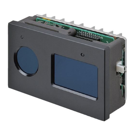
Page 16: Part Names And Functions
- No command operation (initial state): On startup/Under normal operation: Solid ON, On error occurrence: Flashing - With command operation: On startup: Solid ON, Under normal operation/On error occurrence: Can be turned off by a command 3D TOF Sensor Module B5L User's Manual (No. E596) -
Page 17: Dimensions
Chapter 1 Overview 1-5 Dimensions 1-5 Dimensions (Unit: mm) Tolerance class IT Model: J.S.T. Mfg. Co., Ltd. (Coordinate origin) Mounting hole 取付穴 2-M4 (effective depth 8) 3D TOF Sensor Module B5L User's Manual (No. E596) -
Page 18: How To Measure 3D Distance By This Product
The HDR function is enabled and the distance is calculated based on two measurement results. High-speed The HDR function is disabled and the distance is calculated based on one measurement result. Note. HDR function: Function to make multiple measurements by changing the shutter speed 3D TOF Sensor Module B5L User's Manual (No. E596) - Page 19 Note 1. The sample code is for evaluation only. OMRON shall not guarantee operation of the code. Note 2. OMRON is under no obligation to correct any errors or defects in the sample source code under any circumstances, including, but not limited to, changes in the sample code.
- Page 20 Illuminance: 10,000lx min. with sunlight Angle: -43.5°, 0°, +43.5° Measurement distance: 0.5m, 2m, 4m Distance precision Power connector Emitter Receiver Distance (m) Conditions: Target: 70% reflectivity (white paper) Angle: 0° 3D TOF Sensor Module B5L User's Manual (No. E596)
-
Page 21: Procedures
Start of distance measurement, acquisition of Installation & result, stop of measurement by communications, Wiring other acquisition when needed Ch. 3 Communications from Host Command Description ↓ ↓ Power OFF ↓ ↓ Troubleshooting Ch. 5 Troubleshooting 3D TOF Sensor Module B5L User's Manual (No. E596) -
Page 22: Chapter 2 Installation & Wiring
- A measurement target that is highly reflective and in about 12.5 meters or farther away from the product is measured as closer. This product Obstacle (e.g. wall, floor, ceiling) Obstacle (Highly reflective object away from the product) Measurement target 3D TOF Sensor Module B5L User's Manual (No. E596) - Page 23 Design the aperture of the enclosure based on the following dimensions. Customer's enclosure Aperture size of customer's enclosure by thickness [mm] Thickness t = 1 t = 2 t = 3 3D TOF Sensor Module B5L User's Manual (No. E596)
- Page 24 ID for each unit. Refer to "4-13 LED Emission Frequency ID Setting (8EHex)" for details. By default, the LED emission frequency ID is 8. This product This product Measurement target Measurement target Measurement target 3D TOF Sensor Module B5L User's Manual (No. E596)
-
Page 25: Wiring
Separate the mounting holes of this product from the FG. Power supply connection Wire the 24VDC power supply to the power connector shown below. To 24VDC Power connector Housing and contact, J.S.T. Mfg. Co., Ltd. 3D TOF Sensor Module B5L User's Manual (No. E596) - Page 26 30 sec after the power supply voltage exceeds the lower limit of 21.6V After turning on the power again, or when it is restored (when the voltage exceeds 21.6V again), start the command operation in 30 seconds. 3D TOF Sensor Module B5L User's Manual (No. E596)
- Page 27 This product is a USB device connected to the host via a USB cable. The USB connector of this product is micro USB as shown below. - Micro USB compliant (Vbus rating: 0.5A max.) - Vbus power supply must be provided from the host. 3D TOF Sensor Module B5L User's Manual (No. E596)
-
Page 28: Chapter 3 Communications From Host
In such a case, it must be judged as communication timeout. Refer to "3-4 Command List and Response List", "Timeout" for details of communication timeout. 3D TOF Sensor Module B5L User's Manual (No. E596) -
Page 29: Basic Process On Host
(for all range) (91Hex)" for details. - MIN_AMP (for close distance) Low amplitude (weakly reflected light) pixels at far distance make the distance measurement incorrect due to impact of close obstacles, leading to erroneous 3D TOF Sensor Module B5L User's Manual (No. E596) - Page 30 You must be careful about measurement of the followings: - When the distances to the measurement targets vary widely from close to distant - When the reflectivity of the measurement targets vary widely from low to high 3D TOF Sensor Module B5L User's Manual (No. E596)
- Page 31 Note: The distance measurement result cannot be acquired if distance measurement has not been started. ⑥Acquire the results. Execute the Get result command to acquire distance measurement results. ⑦Stop the distance measurement. Execute the Stop distance measurement command to stop measuring the distance. 3D TOF Sensor Module B5L User's Manual (No. E596)
- Page 32 - T3D rotation angle - LED emission frequency ID - MIN_AMP (for all range) - MIN_AMP (for close distance) - Enabling/disabling operation check LED - Responder speed setting (transmission size/interval) - ENR threshold 3D TOF Sensor Module B5L User's Manual (No. E596)
-
Page 33: Command Specifications
As exceptions, the following data have a different value order from the above. For details, refer to respective command description page. - Get result command, distance & amplitude data - Get θφ table command, θφ table data 3D TOF Sensor Module B5L User's Manual (No. E596) -
Page 34: Command List And Response List
- An execution of a command was attempted that cannot be executed during distance measurement. - An execution of a command that can be executed only during distance measurement was attempted while distance measurement is being stopped. 3D TOF Sensor Module B5L User's Manual (No. E596) - Page 35 If the next command is issued while the command is being executed, the issued command will not be accepted, and the system will wait for normal reception after the response to the command being executed is sent. 3D TOF Sensor Module B5L User's Manual (No. E596)
-
Page 36: Chapter 4 Command Description
・ Data details The response is returned when distance measurement has been started and the result can be acquired. By issuing the Get result command during distance measurement, the distance and 3D TOF Sensor Module B5L User's Manual (No. E596) -
Page 37: Stop Distance Measurement (81Hex)
F0Hex By issuing this command during distance measurement, the measurement is stopped. If the distance measurement has not been started, the command is ended normally and the status does not change. 3D TOF Sensor Module B5L User's Manual (No. E596) -
Page 38: Get Result (82Hex)
The data is output in the order of 76799 to 0 from the bottom right to the top left of a 320x240 image. … … 76479 … … 76798 76799 76480 3D TOF Sensor Module B5L User's Manual (No. E596) - Page 39 Amplitude data, returned is the distance data of 320 pixels wide and 240 pixels high with 2 bytes per pixel, followed by amplitude data of 320 pixels wide and 240 pixels high with 2 bytes per pixel. 3D TOF Sensor Module B5L User's Manual (No. E596)
- Page 40 If the result acquisition format is 01FFHex: Amplitude data only, returned is the amplitude data of 320 pixels wide and 240 pixels high with 2 bytes per pixel. Data length Data block 00Hex 02Hex 58Hex 00Hex Data block Amplitude data 76799 76798 76797 … 3D TOF Sensor Module B5L User's Manual (No. E596)
-
Page 41: Set Result Acquisition Format (84Hex)
The unit of distance data is mm (millimeter). When Cartesian coordinate system or rotated Cartesian coordinate system is specified, the distance data output is in PCD (Point Cloud Data) format. Note: PCD (Point Cloud Data) http://pointclouds.org/documentation/tutorials/pcd_file_format.php#pcd-file-format 3D TOF Sensor Module B5L User's Manual (No. E596) - Page 42 The receiving light level exceeds the allowable value of this product and distance measurement is unavailable. Adjust the exposure time shorter. - Overflow Adjust the exposure time shorter. - Low amplitude (less than MIN_AMP) The amplitude value is less than the specified MIN_AMP. 3D TOF Sensor Module B5L User's Manual (No. E596)
-
Page 43: Get Result Acquisition Format (85Hex)
Acquires the output information and coordinate system being specified. Output information: Distance data only Distance data + Amplitude data Amplitude data only Coordinate system: Polar (r) Cartesian (Xo, Yo, Zo) Rotated Cartesian (Xr, Yr, Zr) 3D TOF Sensor Module B5L User's Manual (No. E596) -
Page 44: Set Operation Mode (86Hex)
00Hex 00Hex 00Hex Error: 00Hex 00Hex 00Hex 00Hex FFHex to F0Hex ・ Data details Setting value Data name 00Hex Normal mode 01Hex High-speed mode The default value is 00Hex: Normal mode. 3D TOF Sensor Module B5L User's Manual (No. E596) -
Page 45: Get Operation Mode (87Hex)
00Hex 00Hex 00Hex 01Hex See below for details end: 00Hex Error: 00Hex 00Hex 00Hex 00Hex FFHex to F0Hex ・ Data details Setting value Data name 00Hex Normal mode 01Hex High-speed mode 3D TOF Sensor Module B5L User's Manual (No. E596) -
Page 46: Set Exposure Time (88Hex)
The default values are: - Exposure time : 850 - Frame rate Note: The frame rate is the number of frames per second and is expressed in frames per second (fps). 3D TOF Sensor Module B5L User's Manual (No. E596) -
Page 47: Get Exposure Time (89Hex)
Data is returned in the order from Exposure time (2 bytes), Reserved (4 bytes), and Frame rate (1 byte). Skip the data in the Reserved block. Byte position Data name Exposure time 2 - 5 Reserved (00 x 4, fixed) Frame rate 3D TOF Sensor Module B5L User's Manual (No. E596) -
Page 48: Set T3D Rotation Angle (8Ahex)
Rotation angle around x axis ② Rotation angle around y axis ➀ Rotation angle around z axis ③ Note: The number indicates the The default values are 0 degrees for all. sequence of rotation 3D TOF Sensor Module B5L User's Manual (No. E596) -
Page 49: Get T3D Rotation Angle (8Bhex)
The rotation angles are acquired in the order of x, y, and z as integers (2 bytes). Byte position Data name Rotation angle around x axis Rotation angle around y axis Rotation angle around z axis 3D TOF Sensor Module B5L User's Manual (No. E596) -
Page 50: Set Led Emission Frequency Id (8Ehex)
00Hex 01Hex See below for details end: 00Hex Error: 00Hex 00Hex 00Hex 00Hex FFHex to F0Hex ・ Data details Acquires the LED emission frequency ID, from 0 to 16, currently specified. 3D TOF Sensor Module B5L User's Manual (No. E596) -
Page 51: Set Min_Amp (For All Range)(90Hex)
Specify the minimum amplitude to judge as a valid pixel for all range in 1 byte. If a pixel has an amplitude value smaller than the set value, it is judged as low amplitude. The setting range is 0 to 200. The default value is 0. 3D TOF Sensor Module B5L User's Manual (No. E596) -
Page 52: Get Min_Amp (For All Range)(91Hex)
See below for details end: 00Hex Error: 00Hex 00Hex 00Hex 00Hex FFHex to F0Hex ・ Data details The minimum amplitude value (for all range) currently specified is returned in 1 byte. 3D TOF Sensor Module B5L User's Manual (No. E596) -
Page 53: Set Min_Amp (For Close Distance)(92Hex)
Even if you set a value smaller than the minimum amplitude for the all range, the minimum amplitude for the all range at a close distance is still valid. The setting range is 0 to 200. The default value is 0. 3D TOF Sensor Module B5L User's Manual (No. E596) -
Page 54: Get Min_Amp (For Close Distance)(93Hex)
See below for details end: 00Hex Error: 00Hex 00Hex 00Hex 00Hex FFHex to F0Hex ・ Data details The minimum amplitude value (for close distance) currently specified is returned in 1 byte. 3D TOF Sensor Module B5L User's Manual (No. E596) -
Page 55: Get Θφ Table (94Hex)
As with distance and amplitude data, the data is output in the order of 76799 to 0 from the bottom right to the top left of a 320x240 image. ���� ���� ���� 3D TOF Sensor Module B5L User's Manual (No. E596) - Page 56 The formula for converting θ and φ from fixed-point values to degrees is as follows: θ [degrees] = 90 x θ [fixed-point value]/4096 φ [degrees] = 360 x φ [fixed-point value]/16384 3D TOF Sensor Module B5L User's Manual (No. E596)
-
Page 57: Set Enabling/Disabling Operation Check Led (95Hex)
The status is enabled or disabled immediately after receiving the command. *1: A status in which this product cannot be properly started up due to an error such as a device error. 3D TOF Sensor Module B5L User's Manual (No. E596) -
Page 58: Get Enabling/Disabling Operation Check Led (96Hex)
See below for details end: 00Hex Error: 00Hex 00Hex 00Hex 00Hex FFHex to F0Hex ・ Data details The enabled or disabled status of the operation check LED currently specified is returned in 1 byte. 3D TOF Sensor Module B5L User's Manual (No. E596) -
Page 59: Set Response Speed (97Hex)
If loss of response data occurred, make the transmission size smaller and the interval longer. (The setting may degrade the frame rate) 3D TOF Sensor Module B5L User's Manual (No. E596) -
Page 60: Get Response Speed (98Hex)
See below for details end: 00Hex Error: 00Hex 00Hex 00Hex 00Hex FFHex to F0Hex ・ Data details Acquires the command response speed currently specified. Byte position Data name Transmission size Transmission interval 3D TOF Sensor Module B5L User's Manual (No. E596) -
Page 61: Set Enr Threshold (99Hex)
Lowering the threshold makes it easier to judge an edge, but misjudgments increase when there is a large variation in distance between pixels. You can use 500 as a guideline of the threshold to enable the ENR. 3D TOF Sensor Module B5L User's Manual (No. E596) -
Page 62: Get Enr Threshold (9Ahex)
00Hex 00Hex 02Hex See below for details end: 00Hex Error: 00Hex 00Hex 00Hex 00Hex FFHex to F0Hex ・ Data details Acquires the edge detection threshold (0 to 12499) in 2 bytes. 3D TOF Sensor Module B5L User's Manual (No. E596) -
Page 63: Get Imager Temperature (9Bhex)
2 bytes. The temperature [°C] of the imager is calculated by multiplying the obtained value by a factor of ten. Top left Top right Bottom left Bottom right 3D TOF Sensor Module B5L User's Manual (No. E596) -
Page 64: Get Led Temperature (9Chex)
F0Hex ・ Data details The current LED temperature is returned in 2 bytes. The temperature [°C] of the LED is calculated by multiplying the obtained value by a factor of ten. 3D TOF Sensor Module B5L User's Manual (No. E596) -
Page 65: Initialize Parameters (9Ehex)
If this command is executed, this product is reset and the USB connection is released. After executing this command, there is a waiting time of about 10 seconds before the next command can be accepted. 3D TOF Sensor Module B5L User's Manual (No. E596) -
Page 66: Reset Software (9Fhex)
- ENR threshold If this command is executed, the USB connection is released. After executing this command, there is a waiting time of about 10 seconds before the next command can be accepted. 3D TOF Sensor Module B5L User's Manual (No. E596) -
Page 67: Chapter 5 Troubleshooting
Reset software F0Hex device error product command to restart the (others) unit. Before turning the power back on, please wait for 5 seconds or longer after powering off. 3D TOF Sensor Module B5L User's Manual (No. E596) - Page 68 - When the host OS is Windows 10, delete the unnecessary COM ports then reboot this product and the host. - When the host OS is Ubuntu18, run the following command on the host after 3D TOF Sensor Module B5L User's Manual (No. E596)
- Page 69 Use the Set exposure time values of X, Y, (less than value is less than (88Hex) adjust MIN_AMP) specified exposure time longer. 30000 for all. MIN_AMP. *1: If the operation check LED has been enabled. 3D TOF Sensor Module B5L User's Manual (No. E596)
- Page 70 Get LED Temperature (9CHex) ........64 Output data ..............18 Get MIN_AMP (for all range)(91Hex) ......52 P Get MIN_AMP (for close distance)(93Hex) ....54 Get Operation Mode (87Hex) ........45 Polar coordinate system ..........13 3D TOF Sensor Module B5L User's Manual (No. E596)
- Page 71 Set LED Emission Frequency ID (8EHex) ....50 USB connection ............27 Set MIN_AMP (for all range)(90Hex) ......51 W Set MIN_AMP (for close distance)(92Hex) ....53 Set Operation Mode (86Hex) ........44 Warm-up period ............13 3D TOF Sensor Module B5L User's Manual (No. E596)
- Page 72 Index 5-1 Troubleshooting List E596-E1-01 2020 0820 (0820)(O)
Need help?
Do you have a question about the B5L and is the answer not in the manual?
Questions and answers