
Related Manuals for KLINGER BALLOSTAR KHI


Summary of Contents for KLINGER BALLOSTAR KHI
- Page 1 Issued: 08/2017 KLINGER Fluid Control GmbH Am Kanal 8-10 » 2352 Gumpoldskirchen » Austria office@klinger.kfc.at » www.klinger.kfc.at » Tel: +43 2252 600-0 wT 2860/02 Page 1...
-
Page 2: Table Of Contents
Contents Declaration of Conformity ................3 Individual Parts Designation ................. 4 Proper Use ....................5 Testing of KLINGER Valves ................5 Labeling of the Valves .................. 5 Safety Instructions ..................6 General Notes on Safety ................6 Safety Instructions for Operators ..............6 Hazard Warnings .................. -
Page 3: Declaration Of Conformity
1 Declaration of Conformity wT 2860/02 Page 3... -
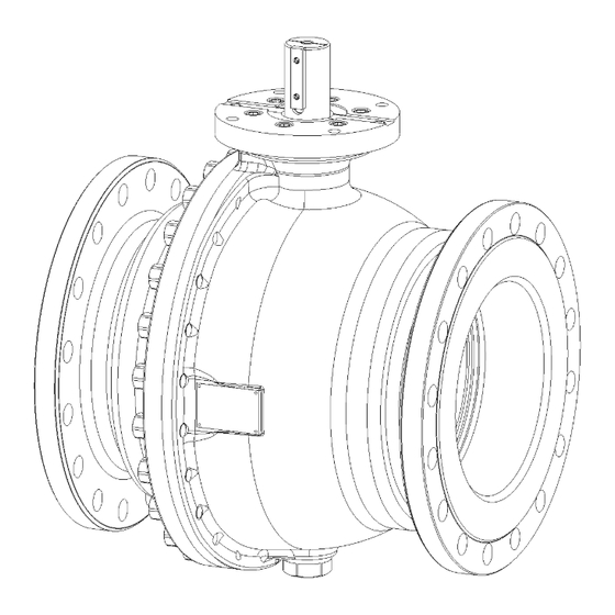
Page 4: Individual Parts Designation
2 Individual Parts Designation DN 125-200 DN 250-1000 Body End piece Operating stem Ball Trunnion Top flange Bush insert, upper part 10. Bush insert, lower part 12. Disc 13. Gasket 14. Gasket 15. Washer 16. Washer 17. O-ring 18. O-ring 19. -
Page 5: Proper Use
Subject to technical alterations and misprints! 4 Testing of KLINGER Valves KLINGER Valves are pressure-tested in accordance with EN 12266-1. The pressure test comprises the tests P10, P11 and P12. Testing the resistance to pressure of the ball (P20) is not included in the standard package. -
Page 6: Safety Instructions
6 Safety Instructions This operation manual must be brought to the attention of the operating personnel. 6.1 General Notes on Safety The safety instructions for valves also apply to the pipeline systems, into which they are installed. This operating manual exclusively focuses on safety instructions, which are to be additionally complied with for valves. -
Page 7: Hazard Warnings
» when applying internal pressure for the first time (pressure test, trial operation) a sufficient safety distance is to be maintained. » it is prohibited to open screw connections (with the exception of those on hand levers and handwheels), when pressurized (medium). »... - Page 8 Electromagnetic radiation hazard: » The hazards resulting from possibly created electromagnetic radiation are to be consulted in the operating manual of the actuator manufacturer. Hazards linked to the operational environment: » The ambient atmosphere and the ambient temperature are to be set in a manner that has no negative influence on the valve, the actuator of the valve, and the medium.
-
Page 9: Technical Data
A P/T diagram is an ideal tool in order to select a suitable valve for pre-defined operational characteristics. The diagrams illustrate all possible limitations of use of KLINGER valves. The area of application for standard valves is from -10 °C up to +200 °C. -
Page 10: Tightening Torques
7.3 Tightening Torques Tightening torques of the split body flange hex nuts (Pos. 32) for standard designs with O-rings and designs with spiral wound gaskets (e.g. KHWI): Tightening torques (Nm) Nominal Dimension VII, VIII, X Spiral wound size gasket 125,150 M 16 M 20 M 22... -
Page 11: Table Of Weights
7.4 Table of Weights This table provides a weight estimation of a PN 40 ball valve with flange connection (full bore). Weight Weight (excl. gear box) (incl. gear box) 85 kg 103 kg 160 kg 180 kg 240 kg 286 kg 410 kg 468 kg 620 kg... -
Page 12: Transportation And Storage
Furthermore, it should be ensured that the valves and possibly mounted actuators have not been damaged during transport. Please also check that the supplied valves (types, nominal sizes etc.) correspond with the order. KLINGER Fluid Control is to be notified immediately of any kind of deviations. Regarding damage obviously resulting from transportation, please contact the freight forwarder in charge of delivery. -
Page 13: Operating Principle
9 Operating Principle Thanks to its "elastic sealing system" the ball valve guarantees absolute tightness in both high-pressure and lowest-pressure scenarios. This is achieved by means of two elastic sealing elements, which work independent of each other. The necessary contact force is achieved a) through pre-stressing during assembly and b) by means of the differential pressure created in the valve (Fig. -
Page 14: Mode Of Operation
10 Mode of Operation During assembly of the body and the end piece, the sealing system is elastically deformed. The two pre-stressed, elastic sealing elements made of stainless steel, together with the sealing rings and a seal at the periphery, create a sealing system with the ball both upstream and downstream of the ball valve. - Page 15 In the closed state of the valve, the ball valve cavity can be discharged and/or vented or depressurized by means of a special sealing system via a test/drain cock. This allows for testing the function of both sealing rings following depressurization (Block & Bleed). Fig.
- Page 16 In order to guarantee the centered orientation of the ball, a trunnion is located on the opposite site. Guided into the vertical bore of the ball by a bearing bush, it is locked in place by a hex screw to counter forces generated within the body. Tightness to atmosphere is achieved through flat gaskets and O-rings.
-
Page 17: Installation And Putting Into Service Regulations
11 Installation and Putting into Service Regulations In order to protect against impurities and damage, the connections of the valves are covered. We recommend removal of these covers only prior to installation. Ballostar® KHI ball valves can be installed in any given orientation. Installation should be executed in the "open"... -
Page 18: Service And Maintenance
The preferred welding methods for the creation of welding seams are: Manual electro-welding MAG / MIG The welding seam sequence is defined as follows: Vertical-down weld: A - C - D - B Rising weld: A - C - B - D 12 Service and Maintenance Maintenance and inspection intervals are to be determined by the operator dependent on the operating mode, as these valves can be utilized under a number of different... -
Page 19: Disassembly Of Individual Parts For Exchange Of Sealing Elements
» Exchange the seals (Pos. 17, 20) in accordance with the spare parts list. Clean the spare parts and treat them with a suitable type of grease to simplify installation » Inspect the bearing surface (Pos. 38). Should any damage be found – exchange the bearings »... - Page 20 » Remove seal (Pos. 19) » Withdraw hexagon head screw (Pos. 35) from trunnion (Pos. 5), remove flat gasket (Pos. 14) » Remove circlip (Pos. 29) from ball hub, remove discs (Pos. 12) for vertical centering » Push trunnion (Pos. 5) into the bore of the ball (careful application of force), remove flat gasket (Pos.13) A washer must be used in the same amount and strength for installation! CAUTION...
-
Page 21: Disassembly Of The Sealing Element
» Carefully remove operating stem (Pos. 3) and bush inserts (Pos. 8, 10) together with sealing rings and bearing bushes out of the body » Manually rotate the ball by 90°, lift out of body, and place on suitable surface material Fig. -
Page 22: Assembly
12.2 Assembly All parts must be cleaned, and, if necessary, lubricated prior to assembly. 12.2.1 Standard Lubricants O-Rings: Silicon grease OKS 1110 Other parts: MOLYKOTE 55 M In special cases, the lubricants designated in the course of the order must be utilized. e.g.: Oxygen applications Klüberalfa YV93-302 Gas applications Klüber Nontrop ZB91 Sterile steam applications Klüberalfa YV91... -
Page 23: Assembly Of The Individual Parts
12.2.3 Assembly of the Individual Parts » Lift ball into body (hub with feather key nut on operating stem side) and place on sealing element » Manually turn ball to the OPEN position » Pre-assemble bush inserts (Pos. 8, 10) with all individual parts (Pos. 15, 17, 20, 38) on operating stem, place feather keys in existing hubs and bolt »... -
Page 24: Inspection Of Axial Orientation Of The Ball
12.2.4 Inspection of Axial Orientation of the Ball In the event that the ball is not correctly aligned in terms of its axial orientation or displays a too large axial freedom of movement, (DN 200 – 400 max. 0.3 mm; DN 500 – 1000 max. -
Page 25: Actuator Mounting
13.1 Fitting the Actuator When fitting actuators, the requirements of the actuator manufacturer have to be mandatorily complied with. The manufacturer of the KLINGER Ballostar® KHI assumes no liability for damage resulting from improper actuator installation. In case of doubt, it is recommended to discuss every actuator installation with the manufacturer of the actuator and the valve. -
Page 26: Spare Parts List
14 Spare Parts List Ball Valve Ballostar® DN 150/125 Individuals Parts Material Pos. Pcs. Dimension Designation VIII Gasket Soft nickel 35/43x1 Gasket Soft nickel 26/36x1 Cushion Joint KFC-25 45/54x1 Cushion Joint K-Sil 46/58x0.3/0.5 O-Ring 43.82x5.33 O-Ring 164.7x3.53 O-Ring / spiral 202.8x3.53 / wound gasket 222.5x206x4.5... - Page 27 Ball Valve Ballostar® DN 200 & 250/200 Individuals Parts Material Pos. Pcs. Dimension Designation VIII Gasket Soft nickel 36/55x1 Gasket Soft nickel 35/46x1 Cushion Joint KFC-25 60/70x1 Cushion Joint K-Sil 61/75x0.3/0.5 O-Ring 59.69x5.33 O-Ring 253.6x3.53 O-Ring / Spiral 304.39x3.53 / wound gasket 344.5x328x4.5 O-Ring...
- Page 28 Ball Valve Ballostar® DN 300 & 350/300 Individuals Parts Material Pos. Pcs. Dimension Designation VIII Gasket Soft nickel 50/65x1 Gasket Soft nickel 36/55x1 Cushion Joint KFC-25 70/80x1 Cushion Joint K-Sil 71/85x0.3/0.5 O-Ring 69.22x5.33 O-Ring 354.97x5.33 O-Ring / Spiral 456.06x3.53 / wound gasket 486.5x470x4.5 O-Ring...
- Page 29 Ball Valve Ballostar® DN 400 & 500/400 Individuals Parts Material Pos. Pcs. Dimension Designation VIII Gasket Soft nickel 61/85x1 Gasket Soft nickel 50/75x1 Cushion Joint KFC-25 90/105x1 Cushion Joint K-Sil 91/110x0.3/0.5 O-Ring 91.44x5.33 O-Ring 456.06x5.33 O-Ring / Spiral 582.68x5.33 / wound gasket 634x604x7.2 O-Ring...
- Page 30 Ball Valve Ballostar® DN 600 & 700/600 Individuals Parts Material Pos. Pcs. Dimension Designation VIII Gasket Soft nickel 75/100x1 Gasket Soft nickel 61/85x1 Cushion Joint KFC-25 120/135x1.5 Cushion Joint K-Sil 122/140x0.3/0.5 O-Ring 120.02x6.99 O-Ring 690x5.33 O-Ring / Spiral 890x5.33 / 929x894x7.2 wound gasket O-Ring 126.37x6.99...
-
Page 31: Disposal
Ball Valve Ballostar® DN 800 Individuals Parts Material Pos. Pcs. Dimension Designation VIII Gasket Soft nickel 90/130x1 Gasket 1.4401 90/120x1 Cushion Joint KFC-25 150/180x2 Cushion Joint K-Sil 151/190x0.3/0.5 O-Ring 151.77x6.99 O-Ring 920x7 O-Ring / Spiral 1220x5.33 / wound gasket 1259x1225x7.2 O-Ring 177.17x6.99 U-Sleeve...
Need help?
Do you have a question about the BALLOSTAR KHI and is the answer not in the manual?
Questions and answers