
Subscribe to Our Youtube Channel
Related Manuals for Luminex GigaCore Series


Summary of Contents for Luminex GigaCore Series
- Page 1 Description: User Manual GigaCore 10. REVISION: 20200204-REV 2.8.4 USER MANUAL GIGACORE PRODUCT FAMILY GigaCore 10 THANKS FOR CHOOSING LUMINEX...
-
Page 3: Table Of Contents
CONTENTS INSTALLATION ..............4 CONFIGURATION ............12 Mounting the device ..............4 Connecting to the web interface ......... 12 Rack mount ..............4 Status Page ................. 12 Rack mount - two devices ........4 Global Page ................13 Truss mount ..............5 RlinkX ................... 17 Wall Mount ..............6 Groups ................... -
Page 4: Installation
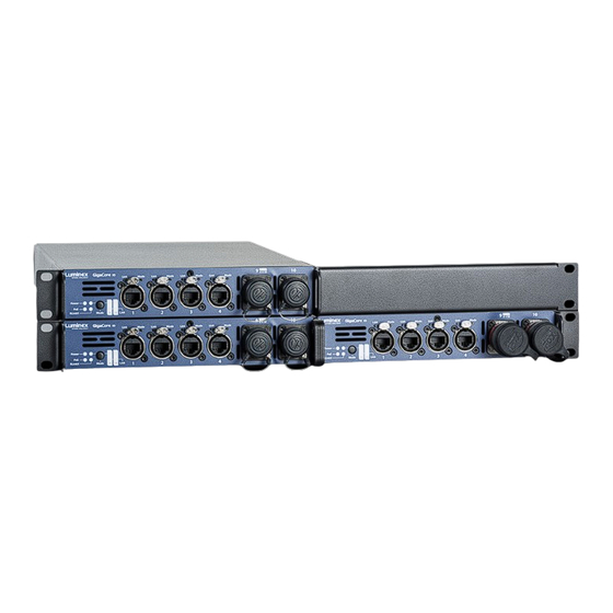
1. INSTALLATION 1.1 Mounting the device GigaCore 10 is a device that can be mounted in a truss as well as in a rack. Please read the following instructions to make sure the device is mounted and secured correctly. RACK MOUNT In case you want to mount your GigaCore 10 in a standard 19-inch rack, you must attach the included mounting ears. -
Page 5: Truss Mount
1 | INSTALLATION / 1.1 MOUNTING THE DEVICE To combine a GigaCore 10 device with a Luminex half 19” device, Screw the bolt, through the LumiNode 4 back ear, into the side style LumiNode 4, the mounting procedure differs a little. -
Page 6: Wall Mount
1 | INSTALLATION / 1.1 MOUNTING THE DEVICE / 1.2POWER UP THE DEVICE WALL MOUNT To mount a GigaCore 10 on the wall, you must attach the wall mount brackets (A) (LU_10_00126). Connect the brackets with 4 screws, re-used from the device. 1.2 Power up the device Power-up the device with a power cable with Neutrik powerCON TRUE1 connection (J) (please contact your local dealer if you don’t have... -
Page 7: Description
1 | INSTALLATION / 1.3 DESCRIPTION 1.3 Description 1.3.1 Front Panel (A) STATUS LEDS: (C) OPTICAL PORT LEDS: Power: Indicates the status of the power supply. 2x Optical Port Mode: According to the selected state, the ƒ ƒ PoE: Indicates the status of the PoE functionality and the PoE LED will show different colours. -
Page 8: Led Indicators
1 | INSTALLATION / 1.4 LED INDICATORS / 1.5 CONNECTION WEB INTERFACE / 1.6 RESET 1.4 LED indicators: The LED indicators of the GigaCore 10 and GigaCore 10 with PoE show With the use of the mode button, the user can get all the necessary the following statuses: information immediately. -
Page 9: Gigacore Features Explained
These features will be explained on the following paragraphs. 2.1 RlinkX: RLinkX, which stands for Redundant Link by LumineX, is an automat- If one of the active paths fails, the switches will enable a redundant ed system to easily create redundant paths between your GigaCore path in a seamless manner. -
Page 10: Groups
2 | GIGACORE FEATURES EXPLAINED / 2.2 GROUPS / 2.3 MULTILINKX 2.2 Groups (VLANs) Light Over IP Converter The groups function allows the user to segment the network into sev- eral virtual networks (VLANs). The main benefit of this function is that Sound Over IP Processor Video Over IP Out no group will affect the other ones, on protocol level. - Page 11 2 | GIGACORE FEATURES EXPLAINED / 2.2 GROUPS / 2.3 MULTILINKX Working with PTPv2 on MultiLinkX When working with PTPv2 (Precision Time Protocol v2), you’ll notice an inverted PTPv2 icon to indicate the PTPv2 enabled port is in an aggre- gation.
-
Page 12: Configuration
(B) Wink: The wink feature allows you to easily identify a GigaCore FACTORY DEFAULT ALL PORTS ARE ASSIGNED TO THE MANAGE- switch in a stack of devices. Click on the Luminex Logo on the switch MENT GROUP. image, all four status LEDs on the left-hand side of the switch will start blinking three times. -
Page 13: Global Page
3 | CONFIGURATION / 3.1 WEB INTERFACE / 3.2 STATUS PAGE /3.3 GLOBAL PAGE 3.3 Global Page The global page consists of four sub menus: 3.3.1 Device settings: (B) ID settings: Set the name of your switch here and add a descrip- This menu allows you to change IP and ID settings of the unit, and the brightness of the front panel’... - Page 14 3 | CONFIGURATION / 3.2 PORT SETTINGS 3.3.2 Port Settings: This menu allows you to change the port’ s speed, add a legend to each port and enable remote monitoring per port. The port speed drop-down menu offers the following options: Disabled: Disable the port.
- Page 15 3 | CONFIGURATION / 3.3.1 UTILITIES 3.3.3 Utilities: This page brings you the tools to reset your device in different ways and set some default security parameters. (A) Reset: This menu allows the user to bring the switch into different (C) Security: The user can use this feature to set a password to protect levels of reset: the access to the web interface.
- Page 16 3 | CONFIGURATION / 3.3.4 FIRMWARE 3.3.4 Firmware: Alternate image: This page brings you the tools to reset your device in different ways and set some default security parameters. To upgrade the switch, click If you’re not satisfied with your recently uploaded firmware you on the Upload Firmware button and select the firmware file you saved can reload the previous firmware version that was installed on on your computer.
-
Page 17: Rlinkx
To provide users with a more advanced and efficient method to re- When a user connects a minimum of two aggregated links between cover topology in case of a link failure, Luminex has developed a new two switches, it is easy to think these are redundant links. However, this method for best link cost calculation in an aggregated network based is seen as a unique link between the switches. -
Page 18: Groups
3 | CONFIGURATION / 3.5 GROUPS 3.5 Groups (VLANs) Groups is a technology which offers the user to easily segment the To assign ports to a group please follow the following steps: network into several virtual networks (VLANs). A. Select the group you wish to assign ports to. Use the coloured This menu allows the user to assign ports to one of the 20 embedded groups of the switch. - Page 19 ƒ protocol. By default, Luminex groups have a default VLAN ID. If In the status page, a stopwatch will be displayed for every port required, the user can change the VID of the group. Be aware set in the group associated to a PTP domain.
-
Page 20: Poe
3 | CONFIGURATION / 3.5.2 MULTILINKX / 3.5.3 TAGGED MANAGEMENT GROUP VID 1 / 3.6 POE 3.5.2 MultiLinkX: MultiLinkX (also known as link aggregation) allows you to gather sever- al links together in order to increase the available bandwidth between switches. - Page 21 3 | CONFIGURATION / 3.6 POE / 3.6.1 POE SETTINGS Two arrows will indicate the following values: Allocated power: based on the classes of the connected PoE Actual usage: a green index will show the current power ƒ ƒ devices, the switch will allocate the necessary power to the delivered by the PoE supply.
-
Page 22: Profile Manager
3 | CONFIGURATION / 3.7 PROFILE MANAGER 3.7 Profile Manager The profile manager allows the user to easily save / recall / export or A maximum of ten profiles can be saved on a GigaCore switch. import a configuration. The switch also offers to export or import a profile through a comput- A profile will contain the following parameters: er, providing the user with an easy way to exchange profiles between switches. - Page 23 3 | CONFIGURATION / 3.7 PROFILE MANAGER / 3.7.2 RECALL A PROFILE / 3.7.3 EXPORT A PROFILE / 3.7.4 IMPORT A PROFILE / 3.7.6 DEFAULT PROFILE 3.7.2 Recall a Profile: To recall a profile, select it amongst the ten available profiles in the up- per tab.
-
Page 24: Reset
In the case you need to reset the unit without the web interface, the ƒ GigaCore 10 and GigaCore 10 with PoE offers different levels of reset, the state it left Luminex and ALL data will be erased. based on the ones you can find in the web interface. Default login: admin... -
Page 25: Factory Reset
If you need to ask our team for more help or you need to return a de- tion. There is a knowledge base available online that gets updated on vice to Luminex for diagnostics or repair, you can also find the option a regular basis at: https://support.luminex.be... - Page 27 YOUR NETWORK SOLUTION FOR AUDIO, VIDEO AND LIGHTING EFFECTIVE, RELIABLE, ACCESSIBLE...
- Page 28 Slamstraat 13 | 3600 Genk | Belgium | T +32 11 812 189 | info@luminex.be | www.luminex.world...
Need help?
Do you have a question about the GigaCore Series and is the answer not in the manual?
Questions and answers