
Related Manuals for Luminex LumiCore


Summary of Contents for Luminex LumiCore
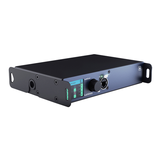
- Page 1 Description: User Manual LumiCore. REVISION: 20220629-REV 2.4.1 USER MANUAL LUMICORE PRODUCT FAMILY LumiCore THANKS FOR CHOOSING LUMINEX...
-
Page 2: General Information
IMPORTANT NOTICE: DO NOT MODIFY THIS UNIT! This product, when installed as indicated in the instructions contained in this manual, meets FCC requirements. Modifications not expressly approved by Luminex Lighting Control Equipment nv may void your authority, granted by the FCC, to use the product. -
Page 3: Warranty Information
Returning under warranty Any product unit or parts returned to Luminex LCE must be packaged in a suitable manner to ensure the protection of such product unit or parts, and such package shall be clearly and prominently marked to indicate that the package contains returned product units or parts. -
Page 4: Table Of Contents
Table of Contents GENERAL INFORMATION ......2 WARRANTY INFORMATION ......3 1. - Page 5 5. WEB API ........26 6. LUMICORE IN DETAIL ......27 What is a process engine? .
-
Page 6: Applications
1. Applications 1. Applications A few examples of applications where the LumiCore can be used: ƒ Touring & Live events ƒ Studio’s ƒ Cruise ships/Yachts ƒ Theatres ƒ Arena/Stadium lighting ƒ Architainment lighting ƒ Theme parks ƒ Campuses ƒ Houses of Worship ƒ... -
Page 7: Installation
2. Installation 2.1 mounting the device LumiCore is a device that can be mounted in a truss as well as in a rack. Please read the following instructions to make sure the device is mounted and secured correctly. RACK MOUNT In case you want to mount your LumiCore in a standard 19-inch rack, you must attach the included mounting ears. -
Page 8: Truss Mount
TRUSS MOUNT To mount a LumiCore in a truss, you must attach a M10 clamp (G) to the M10 insert (H). After that, you can F I R S T A N G L E P R O J E C T I O N mount the clamp to the truss bars. -
Page 9: Power Up The Device
AC power fails. 2.3 Connection to the network To get the LumiCore online in your system, connect either port ETH1 or ETH2 to a computer, or to a port of an Ethernet switch. Only port ETH2 on the rear of the unit can be used to power the unit through PoE. Check the port labelling... -
Page 10: Led Indicators
2 | InstallatIon 2.4 leD indicators There are various LEDs on the LumiCore. Here is a list of the LEDs, the possible colours, and the meaning of each colour: NETWORK PORT Left LED (Link) Green Gigabit connection (flashing: Ethernet traffic) -
Page 11: Reset
ƒ With a computer connected to the device, open LumiNet Monitor (version 2.3.3 or above). ƒ Under Tools in the menu bar you find Reset LumiCore. ƒ Enter the MAC address of the device you want to reset. This can be found on the label with the IP address or via the web-UI. -
Page 12: Configuration
3.1 node Page (A) Identify: Clicking on the Luminex logo will identify your LumiCore in the network. The LCD display will turn green and the Mode LED will flash green for 5 seconds. In the web-UI you get the text “Identified”... -
Page 13: How To Reset A Process Engine
3 | ConfIGUratIon HOW TO RESET A PROCESS ENGINE To reset a process engine, follow the following steps: ƒ Hover your mouse over the top left corner of the process engine and select the tick box. ƒ Click on the trashcan icon at the top right corner above the first process engine. A blank process engine appears as follows: If you want to reset all the process engines at once, navigate to the top left above the first process engine and select the tick box “Select all Process Engines”... -
Page 14: How To Copy A Process Engine
Click and drag the handle down, to select other process engines. The LumiCore will automatically increase the universe number for each following process engine. This allows you to create a complete configuration in a snap! 3.2 Play page... -
Page 15: Record Trigger
If the IP address 0.0.0.0 is used all devices in the network generating the assigned control protocol and universe can be the control source. The LumiCore will use an LTP merging policy between the first four sources that become available. When using sACN the priority is also important to consider. -
Page 16: Miscellaneous
3 | ConfIGUratIon Protocol can be Art-Net or sACN. Universe is the universe created by the contact closure. Destination IP/Priority allows you to broadcast or unicast the contact closure’s universe when using Art-Net. If no IP is entered the broadcast address will be auto filled. When sACN is chosen as protocol this becomes the priority. -
Page 17: Network
This can be useful when data from different applications, in coexistence with the lighting data, needs to be transported over the same network. The Lighting data input/output and the management of the LumiCore can be separated in different network groups and can each have a unique IP address. - Page 18 4 for the input/output interface. Finally, we assigned group 2 to ETH1 to give the user access to this group on the front of the LumiCore. When all the settings are done, click Save (N) to apply the configuration.
-
Page 19: Scenario 3(C): Separate Vlans For All Interfaces
This can be useful when data from different applications, in coexistence with the lighting data, needs to be transported over the same network. The lighting data input, the lighting data output, and the management of the LumiCore can be separated in different network groups and can each have a unique IP address. - Page 20 Network ports: Depending on the configuration chosen for the interfaces we now need to assign the correct groups/ trunks to the Ethernet ports of the LumiCore. ƒ Select the group or trunk you wish to assign in the Group/Trunks window (F).
-
Page 21: Group/Vlan Advanced Settings
3 | ConfIGUratIon GROUP/VLAN ADVANCED SETTINGS To change the settings for a group, click on the Edit group option in the Group/Trunks section. With a group selected you can: ƒ Change the VLAN ID. ƒ Change the name for ease of identification. ADD OR EDIT A TRUNK To Add or Edit a Trunk, click the Edit Trunk option in the top right of the Group/Trunks section. -
Page 22: Toolbox Page
When a profile has been selected the user can scroll down to the bottom of the profile preview to see the IP settings in this profile. By default, the LumiCore will NOT load the IP settings that are stored in the profile. If you want to load the IP settings saved in the profile, slide the Preserve IP settings to OFF. -
Page 23: Reset
3 | ConfIGUratIon ƒ Select the file you have extracted. ƒ The LumiNode will start the firmware upgrade. The unit will reboot after the upgrade is completed. RESET In this panel, you can reset the LumiNode, with two separate options: ƒ... -
Page 24: Lcd Display
From firmware version 2.0 onwards the LCD display has been activated and the following information can be found on the display. IIn normal operation the LumiCore will step through the process engine overview pages. The display will change every 5 seconds. - Page 25 4 | lCD DIsPlay If the advanced network has been configured and the user is accessing the network setting via the display, the following popup will appear to warn the user: The front-end display offers access to most of the settings in the unit. Menu tree view: Home ƒ...
-
Page 26: Web Api
5. Web API 5. Web API The LumiCore range supports the use of Web API. For a detailed list of available actions via Web API, please type the following in your favourite web browser: http://IP_OF_YOUR_DEVICE/api/doc... -
Page 27: Lumicore In Detail
6. LumiCore in detail 6. LumiCore in detail The LumiCore series is a new range of network converter, inheriting more than a decade of experience from the Luminex Ethernet-DMX converter design and manufactoring. In the past, most of the people were designing their system according to the number of universes and DMX ports they would need on their lighting control system. -
Page 28: Input
Next to the Source IP field you find a cog wheel for advanced settings: ƒ Accept Own Data. In some cases, it is required to ignore the Art-Net data generated by the LumiCore itself. When disabled the LumiCore will only listen to other sources in the network. - Page 29 Next to the Source IP field you find a cog wheel for advanced settings: ƒ Accept Own Data. In some cases, it is required to ignore the KiNET data generated by the LumiCore itself. When disabled the LumiCore will only listen to other sources in the network.
-
Page 30: Output
First select which show you want to use, then select the process engine that you want to use. All the process engines of the LumiCore are always available to choose from. For a better identification of the source, you can add a text to your Play source. - Page 31 (default 0) and the port number you wish to send this universe to. You can specify the IP address of the destination, by ticking the Unicast box. By default, the LumiCore will transmit this KiNET universe to the broadcast address of the IP range the unit is part of.
-
Page 32: Mode Definition
Auto Recover: ƒ When auto recovery is enabled the LumiCore will switch back to input one as soon as this is back available in the network. In this case the warning for the missing backup control source can be ignored. - Page 33 6 | lUmICore In DetaIl X-FADE This mode offers to you to cross fade between two sources. Ideal in a situation where you need to cross fade between a lighting desk and a media server, the control channel allows you to keep full control on the speed and smoothness of the transition.
- Page 34 6 | lUmICore In DetaIl CUSTOM This mode is ideal for a complex setup, or when per channel control is needed. Custom offers you to choose what policy to apply for each channel, and to create a complete custom soft patch.
-
Page 35: Patch Option
Press Apply to save your settings. PATCH IMPORT/EXPORT From firmware 2.2.0 LumiCore offers the option to import or export your patch. You can import a CSV or TSV file with your custom patch. The process engine will automatically configure the mode required based on your patch info. -
Page 36: Master/Limit Explained
6 | lUmICore In DetaIl You can define the control channel, the protocol and universe number, as the IP address of the control source. Click on the gear wheel icon to change these parameters. From there, you can apply any master /limit control channel to your output channels. This can be the same for all channels or different per channel or group of channels. -
Page 37: Startup Buffer
LumiCore on bootup until the input source has been detected. As soon as the first frame from the input source is present on the input, the LumiCore will switch to the input source. -
Page 38: Technical Support
If you need to ask our team for more help or you need to return a device to Luminex for diagnostics or repair, you can also fi nd the option on this page to request an RMA or start a support ticket. -
Page 39: Credits
8. Credits The following credits are available for this manual: ƒ Art-Net™ Designed by and Copyright Artistic Licence Holdings Ltd. ƒ ANSI E1.20 - 2010 Entertainment Technology RDM, Remote Device Management over DMX512 Networks. ƒ ANSI E1.31 - 2018 Entertainment Technology - Lightweight streaming protocol for transport of DMX512 using ACN. -
Page 40: Technical Specifications
9. Technical Specifications 9. Technical Specifications CONNECTIVITY Network 2x gigabit shielded Neutrik etherCON connector Contact Closure 1x 2-pin plugable terminal block 1x Neutrik powerCON TRUE1 Power PoE-802.3af (Class 0) ETHERNET FEATURES Art-Net (1-4) sACN ANSI E1.31-2018 Supported protocols RTTrPL (BlackTraX) KiNET v1, v2 Port speed 10/100/1000Mbps... - Page 41 9 | teCHnICal sPeCIfICatIons MANAGEMENT Built in Web server Configuration Documented Web API Colour display & Jog ENVIRONMENTAL Operating temperature 0 to +50°C Storage temperature -10 to +70°C Humidity (non condensing) 5 to 95% RH MECHANICAL Enclosure Robust all metal housing Dimensions (W x D x H) 220 x 175.3 x 44mm Weight...
-
Page 42: Disclamer
9 | teCHnICal sPeCIfICatIons DISCLAMER Luminex LCE operates a policy of continuous development. Luminex LCE reserves the right to make changes and improvements to any of the products described in this document above without prior notice. Specifications are subject to change without notice. - Page 43 YOUR NETWORK SOLUTION FOR AUDIO, VIDEO AND LIGHTING EFFECTIVE, RELIABLE, ACCESSIBLE...
- Page 44 Slamstraat 13 | 3600 Genk | Belgium | T +32 11 812 189 | info@luminex.be | www.luminex.be...
Need help?
Do you have a question about the LumiCore and is the answer not in the manual?
Questions and answers