Sign In
Upload
Manuals
Brands
KAESER Manuals
Air Compressor
EPC-G Series
KAESER EPC-G Series Manuals
Manuals and User Guides for KAESER EPC-G Series. We have
1
KAESER EPC-G Series manual available for free PDF download: Assembly And Operating Manual
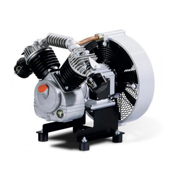
KAESER EPC-G Series Assembly And Operating Manual (102 pages)
1-stage piston compressor
Brand:
KAESER
| Category:
Air Compressor
| Size: 5.94 MB
Table of Contents
Table of Contents
3
1 Regarding this Document Using this Document
11
Further Documents
11
Copyright
11
Symbols and Labels
11
Warnings
11
Tab. 1 Danger Levels and Their Definition (Personal Injury)
11
Potential Damage Warnings
12
Other Alerts and Their Symbols
12
Tab. 2 Danger Levels and Their Definition (Damage to Property)
12
2 Technical Specifications Nameplate
14
Options
14
Mass
14
Tab. 3 Nameplate
14
Tab. 4 Options
14
Compressor Block
15
Ambient Conditions
15
Ventilation
15
Tab. 5 Mass
15
Tab. 6 Compressor Block
15
Tab. 7 Ambient Conditions
15
Pressure
16
Noise Emission [Db(A)]
16
Tab. 8 Ventilation
16
Tab. 9 Cylinder Relief Valve - Pressure Data
16
Tab. 10 Collecting Pipe Relief Valve Setting
16
Motor Power and Speed
17
Compressor Oil Recommendation
17
Tab. 11 Noise Emission [Db(A)]
17
Tab. 12 Motor Power and Speed
17
Tab. 13 Permissible Starting Frequency
17
Compressor Oil Charge
18
Electrical Connection
18
Three-Phase Power Supply
18
Tab. 14 Compressor Oil Recommendation
18
Tab. 15 Compressor Oil Charge
18
Tab. 16 Supply Details 230V / 3 / 50Hz
19
Tab. 17 Supply Details 400V / 3 / 50Hz
20
Tab. 18 Supply Details 500V / 3 / 50Hz
20
Tab. 19 Supply Details 690V / 3 / 50Hz
21
Tab. 20 Supply Details 230V / 3 / 60Hz
21
Tab. 21 Supply Details 380V / 3 / 60Hz
21
Electrical Connection Data for Oil Level Monitoring
22
Tab. 22 Supply Details 440V / 3 / 60Hz
22
Tab. 23 Supply Details 460V / 3 / 60Hz
22
Tab. 24 Option C5: Connection Data for Oil Level Monitoring
22
Mains Conditions
23
Supply Conditions at 400V/3/50Hz
23
Machine Duty Cycle
23
Tab. 25 Network Impedance
23
Tab. 26 Machine Duty Cycle
24
3 Safety and Responsibility Basic Instructions
25
Specified Use
25
Improper Use
25
User's Responsibilities
26
Observe Statutory and Universally Accepted Regulations
26
Determining Personnel
26
Keeping to Inspection Schedules and Accident Prevention Regulations
26
Dangers
27
Safely Dealing with Sources of Danger
27
Safe Machine Operation
29
Organisational Measures
31
Danger Areas
31
Safety Devices
32
Safety Signs
32
Fig. 1 Location of Safety Signs
32
Tab. 27 Danger Areas
32
Information Signs
33
In Emergency
33
Correct Fire Fighting
33
Tab. 28 Safety Signs
33
Tab. 29 Information Signs
33
Injury from Handling Compressor Oil
34
Warranty
34
Environment Protection
35
4 Design and Function
36
Outline of the Machine
36
Machine Structure
36
Machine Function
36
Fig. 2 Machine Overview
36
Options
37
Oil Level Monitoring
37
Silenced Air Filter
37
Air Filter with Plastic Casing
37
Fig. 3 Option C5: Oil Level Monitoring
37
Fig. 4 Option H9: Silenced Air Filter
37
Castors
38
Screwable Rubber Pads for Air Receiver Mounting
38
Fig. 5 Option H10: Air Filter with Plastic Casing
38
Fig. 6 Option H14: Castors
38
Fig. 7 Option H20: Screwable Rubber Pads
38
Screwable Rubber Pads
39
Operating Modes and Control Modes
39
Machine Operating Modes
39
External Control Unit
39
Fig. 8 Option H29: Screwable Rubber Pads
39
Safety Devices
40
Safety and Regulating Devices
40
Accessories
41
5 Installation and Operating Conditions
42
Ensuring Safety
42
Installation Conditions
42
Determining Location and Clearances
42
Ensuring the Machine Room Ventilation
43
Fig. 9 Recommended Machine Placement and Dimensions [MM]
43
Prevention of Thermal Problems
44
Operating the Machine in a Compressed Air Network
44
6 Installation
45
Ensuring Safety
45
Reporting Transport Damage
46
Fitting the Rubber Pads
46
Replacing the Air Filter
46
Fig. 10 Fitting the Rubber Pads
46
Fig. 11 Replacing the Air Filter
46
Connecting the Machine with the Compressed Air Network
47
Installing the Venting Valve
47
Fig. 12 Compressed Pipework
47
Installation Examples
48
Safety and Control Devices
48
Fig. 13 Install the Venting Valve On-Site
48
Fig. 14 Typical Installation of Safety and Regulating Devices
49
Two Machines with One Air Receiver
50
Connecting the Machine to the Power Supply
50
Fig. 15 Typical Installation of Two Machines with One Air Receiver
50
Options
51
Oil Level Monitoring
51
Fig. 16 Option C5: Oil Level Monitoring
52
Tab. 30 Option C5: Oil Level Monitoring Factory Setting
52
Fig. 17 Option C5: Changing the Oil Level Monitoring Setting
53
Mounting the Machine on an Air Receiver
54
Anchoring the Machine
54
Retrofitting the Sound Enclosure (Accessory)
54
Fig. 18 Option H20: Screwable Rubber Pads
54
Fig. 19 Option H29: Securing the Screwable Rubber Pads
54
Dismantling the Sound Enclosure
55
Fitting the Sound Enclosure
55
Fig. 20 Exchanging the Base Plate of the Compressor Block in an EPC 340-G
56
Fig. 21 Fitting the EPC 340 Sound Enclosure
57
Fig. 22 Replacing the Compressor Block's Base Plate and Modifying the Air Filter, EPC 440-G
58
Fig. 23 Fitting the EPC 440 Sound Enclosure
59
Fig. 24 Modifying the Air Filter, EPC 630-G / EPC 840-G
60
Fig. 25 Installing the Sound Enclosure, EPC 630-G / EPC 840-G
61
Fig. 26 Modifying the Air Filter, EPC 1100-G / EPC 1500-G
62
Fig. 27 Installing the Sound Enclosure, EPC 1100-G / EPC 1500-G
63
7 Initial Start-Up Ensuring Safety
65
Instructions to be Observed before Commissioning or Re-Commissioning
66
Checking Installation and Operating Conditions
66
Tab. 31 Re-Commissioning after Storage
66
Motor Protection
67
Motor Protection Setting by Direct Online Starting
67
Motor Protection Setting by Star-Delta Starting
67
Tab. 32 Check List of Installation Conditions
67
Checking the Direction of Rotation
68
Starting the Machine for the First Time
68
Measuring the Air Receiver Filling Time
68
Tab. 33 Air Receiver Filling Time
68
8 Operation
69
Switching on and off
69
Direct Start
69
Fig. 28 Switching the Compressed Air Station on and off
69
Direct Online Start with Solenoid Valve
70
Star-Delta Start
70
9 Fault Recognition and Rectification
72
Basic Instructions
72
Faults
72
Tab. 34 Faults and Remedies
74
10 1 Maintenance
75
Ensuring Safety
75
Following the Maintenance Plan
76
Logging Maintenance Work
76
Regular Maintenance Tasks
76
Compressor Oil Change Interval
76
Tab. 35 Regular Maintenance Tasks
76
Regular Service Tasks
77
Maintaining the Air Cooler or Fan Cowl
77
Tab. 36 Compressor Oil Change Intervals
77
Tab. 37 Regular Service Tasks
77
Cleaning the Air Cooler or Fan Cowl
78
Air Filter Maintenance
78
Fig. 29 Cleaning the Air Cooler or Fan Cowl
78
Air Filter (Sound Damping) Maintenance
79
Fig. 30 Air Filter Maintenance
79
Fig. 31 Option H9: Air Filter (Sound Damping) Maintenance
79
Air Filter (Plastic Housing) Maintenance
80
Fig. 32 Option H10: Air Filter (Plastic Housing) Maintenance
80
Drive Motor Maintenance
81
Checking the Oil Level
81
Topping up the Compressor Oil
81
Fig. 33 Checking the Oil Level
81
Changing the Compressor Oil
82
Fig. 34 Topping up the Compressor Oil
82
Check the Pressure Relief Valve
83
Pressure Relief Valves on the Cylinder Head, Collecting Pipe and Air Cooler
83
Fig. 35 Changing the Compressor Oil
83
Venting the Machine (De-Pressurising)
84
Fig. 36 Checking the Pressure Relief Valves on the Cylinder Head, Collecting Pipe and Air Cooler
84
Solenoid Valve Maintenance
85
Cleaning the Solenoid Valve
86
Fig. 37 Cleaning the Solenoid Valve
86
Replacing the Solenoid Valve
87
Cylinder Head and Valves
87
Checking Cylinder Head and Valves
87
Fig. 38 Replacing the Solenoid Valve
87
Cleaning the Cylinder Head and Valves
88
Starting the Machine and Performing a Trial Run
88
Tab. 38 Tightening Torque for Cylinder Head Screws
88
Documenting Maintenance and Service Work
89
Tab. 39 Logged Maintenance Tasks
89
11 Spares, Operating Materials, Service
90
Note the Nameplate
90
Ordering Consumable Parts and Operating Fluids/Materials
90
Fig. 39 Consumable Parts
90
Tab. 40 Consumable Parts
90
Kaeser Air Service
91
Replacement Parts for Service and Repair
91
12 1 Decommissioning, Storage and Transport
92
Commissioning
92
Packing
92
Storage
93
Transport
93
Safety
93
Transport with a Forklift Truck
93
Transport with a Crane
93
Fig. 40 Transporting with a Forklift Truck
93
Disposal
94
Fig. 41 Transporting with a Crane
94
13 Annex
95
Pipeline and Instrument Flow Diagram (P&I Diagram)
95
Dimensional Drawing
98
Advertisement
Advertisement
Related Products
KAESER EPC Series
KAESER EPC 230-2-100
KAESER EPC 420-2-250
KAESER EPC 550-2-250
KAESER EPC 550-2-350
KAESER EPC 750-2-500
KAESER EPC 1000-2-500
KAESER EPC 440-G
KAESER EPC 630-G
KAESER EPC 840-G
KAESER Categories
Air Compressor
Compressor
Controller
Dryer
Construction Equipment
More KAESER Manuals
Login
Sign In
OR
Sign in with Facebook
Sign in with Google
Upload manual
Upload from disk
Upload from URL