ARRI Orbiter Safety And Installation Manual
Hide thumbs
Also See for Orbiter:
- Short instruction (12 pages) ,
- User manual (12 pages) ,
- Short manual (6 pages)
Table of Contents
Advertisement
Quick Links
Advertisement
Table of Contents

Related Manuals for ARRI Orbiter


Summary of Contents for ARRI Orbiter
- Page 1 S A F E T Y A N D I N S T A L L A T I O N M A N U A L L5.0021114 09 / 2020...
- Page 2 This device contains open source software. The associated license texts can be retrieved via the web interface of the device. To access the web interface of the device, please connect the Orbiter to your network and call the following address in the web browser: http://<IP address of the Orbiter>/licenses/.
-
Page 3: Dimensions
Dimensions All dimensions in mm (above dimension line) and inch (below dimension line) -
Page 4: Table Of Contents
To Power and use the Orbiter ........ -
Page 5: Safety Information
Safety Information Always f ollow these instructions and instructions printed on the product or given in the documentation shipped with the product to protect against injury to yourself and damage to the product or other objects. Risk Levels and Alert Symbols Safety warnings, safety alert symbols, and signal words in these instructions indicate different risk levels: DANGER DANGER indicates an imminent hazardous situation which, if not avoided, will result in death or... -
Page 6: Vital Precautions
Maintenance and repair work is only to be carried out by an authorized ARRI service center. Improper repair attempts can be life-threatening. Never bypass or remove any safety feature of the product. -
Page 7: Warnings
Warnings WARNING! Humidity and condensation. Risk of electric shock and fire. Never expose the product to rain or moisture. Do not use the product for 2 h when it was exposed to big temperature differences as condensed moisture may damage the product electrically when switched on. -
Page 8: General Precautions
General Precautions NOTICE The ARRI Orbiter is intended for professional use and may only be operated by qualified persons. It is not intended for household use. Please follow the user manual of accessories and third party accessories such as battery packs and battery chargers. -
Page 9: To Replace The Light Source
Only use disinfectants with a maximum alcohol content of 70% to disinfect the product Firmware NOTICE Check regularly on the ARRI Orbiter website if a new firmware version is available for the Orbiter. For best performance we strongly recommend to use the fixture with the latest firmware available. Intended Use NOTICE This product is intended to illuminate persons and objects in a dry environment. -
Page 10: Introduction
Orbiter is designed for direct or indirect illumination of objects. The high output allows a large distance of the light source to the object. Like all ARRI LED products, the Orbiter has a fully tunable light source. The Orbiter produces white or colored light with adjustable color temperature and adjustable green-magenta point. -
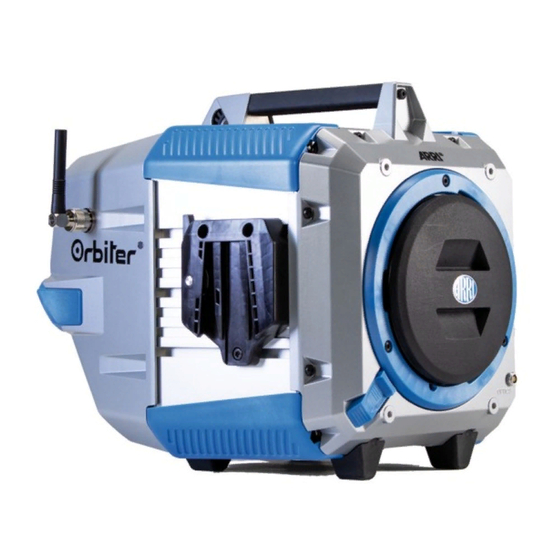
Page 11: Overview
Overview Orbiter (delivery state) Quick Lighting Mount QLM Orbiter with manual yoke & control panel* Safety Loop Attachment Yoke Spigot (junior pin) Upper handle Protective cap Rubber feet Locking slider Quick release lever Yoke bracket Antenna (wireless DMX) Communication interface (5-pin Lemo) -
Page 12: Physical Installation
Physical Installation WARNING! Risk of falling! Risk of injury. Attach an approved safety cable to secure the product and accessories against clamp or bracket failure when the product is mounted above floor. The safety cable needs to be approved at least 10 times the weight of the product including all accessories mounted at the product. -
Page 13: To Mount The Yoke
Both yoke versions feature the quick release system for mounting and removing the yoke without a tool. • Place the Orbiter on a smooth, stable surface or mount the stirrup on a tripod. • Align the yoke adapters of the yoke (4, short side down). -
Page 14: Basic Features
Loose the mounting screw of the tripod or the appropriate fixing screw of the mounting clamp to pan the Orbiter. Tighten the screw to avoid unintended movement. Loose both tilt lock levers (21) to tilt the Orbiter to the desired angle. Tighten the both tilt lock levers to avoid unintended movement. -
Page 15: Wireless Dmx
The USB-C port (23) is used to connect the Orbiter to a PC / notebook for service purpose. USB Ports on the Front Side The Orbiter has two USB ports (10, 11) on the front side for recognition of the mounted optics and for com- munication with optical accessories. -
Page 16: To Connect And Disconnect The Control Panel Cable
Orbiter initializes for a few seconds and is ready for operation. The Orbiter will operate with the settings made on the fixture menu or received by DMX / RDM, Art-Net or sACN. Please observe the information in the following section. -
Page 17: Power Source
You can hard-wire the Orbiter to a building electrical installation. Power outlets or external power switches that supply the Orbiter with power must be located near the fixture and easily accessible so that the fixture can easily be disconnected from power. Alternatively you can use a mains cable with inline main switch and suitable mains plug. -
Page 18: To Connect A Battery Pack
• To unlock the cable connector, push the connector lock backwards and turn the cable connector counter- clockwise. Pull the cable connector out of the power input socket. To Connect a Battery Pack The Orbiter can be used with a battery pack independent of AC power. The battery pack must meet the following specifications: Output voltage... - Page 19 Orbiter. If the battery pack does not have a switch for switching on and off, the brightness of the orbiter should be set to zero before disconnecting the connector cable to the battery pack. This will reduce the load on the connectors and increase the lifetime of the connectors.
-
Page 20: Dmx
Pin 5 = DMX Data + (hot) Pins 4 and 5 are not used by the Orbiter but are bridged between input and output sockets. These pins can therefore be used as a pass-through connection for an additional data signal if required. -
Page 21: Specification
Type ........ - Page 22 4,5 m 15,6 m Accessories Please find a detailed overview of all accessories available in the „Orbiter Accessories Guide“ and on the ARRI website. Specification subject to change without notice. For the latest product specification including photometric data, see www.arri.com.
- Page 23 Certifications and Safety Standards (in progress) International (IECEE CB Scheme) ..........EN / IEC 60598-2-17 .
- Page 24 Kanada (SCC, IC) CAN/CSA C22.2 No. 166 CAN/CSA C22.2 No. 9.0S1 CAN/CSA-C22.2 No. 250.13 CAN ICES-3 (A)/NMB-3(A) ICES-003 RSS 210 1. This device complies with Industry Canada’s licence-exempt RSSs. Operation is subject to the following two conditions: (1) This device may not cause interference; and (2) This device must accept any interference, including interference that may cause undesired operation of the device.
Need help?
Do you have a question about the Orbiter and is the answer not in the manual?
Questions and answers