Table of Contents
Advertisement
Advertisement
Table of Contents

Related Manuals for Pronomic Lift&Drive 90IE


Summary of Contents for Pronomic Lift&Drive 90IE
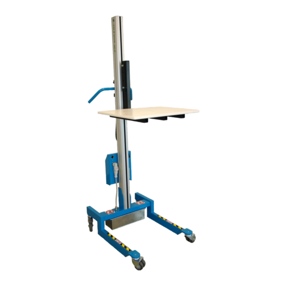
- Page 1 Lift trolley Lift&Drive 90IE / 90JE Original instructions...
- Page 2 It is important that you read and understand the manual before using the lift trolley. Do you have any questions? – Please contact the distributor or the manufacturer. Pronomic AB Visiting address: Postal address: Domherrevägen 15 Box 5504 192 55 Sollentuna...
-
Page 3: Table Of Contents
Contents Description of the lift trolley ....................4 Warranty ............................4 Components ..........................4 Assembly ..........................6 Disassembly and scrapping ......................6 Using the lift trolley ......................7 Handlebar ............................ 7 Remote control ..........................7 Power pack ..........................8 Brakes ............................8 Directional lock .......................... -
Page 4: Description Of The Lift Trolley
Damage due to misuse or incorrect use of the equipment will void the warranty. 1.2 Components The lift trolley consists of a number of modules. The locations of these are shown in the image on the next page. Please contact Pronomic for information regarding part numbers. ... - Page 5 ________________________________________________________________________________ 5 – Lift trolley Lift&Drive 70IE / 90IE / 90JE...
-
Page 6: Assembly
To disassemble the lift trolley, follow the instructions in section Assembly, but in reverse order. When the lift trolley is due for scrapping the machine, complete with batteries, should be handed in to a recycling centre or Pronomic to ensure reuse and safe handling of all parts. ________________________________________________________________________________... -
Page 7: Using The Lift Trolley
3 Using the lift trolley If the load is left on the lifter for some time it may be necessary to lower the load before it can be raised. 3.1 Handlebar To achieve a good working position the handlebar should be adjusted to a correct height. The handlebar can easily be adjusted in height by loosening the black knobs on the handlebar. -
Page 8: Power Pack
The remote control should be placed to allow the user to easily press the buttons or to control the lever. The bracket for the remote control is fitted to the handlebar. The bracket can easily be moved by turning the black knob counter-clockwise. The bracket can be locked in any position on the handle by turning the knob clockwise. -
Page 9: Loading And Unloading
Further use requires more frequent service intervals. Only spare parts supplied or approved by Pronomic may be used. After disassembly/assembly of the column or load carrier a load test should be performed, see section Assembly. -
Page 10: Every Year, Or When Needed
For lift trolleys with a power pack equipped with a voltage indicator a flashing bar on the voltage indicator means that the batteries need charging. If the lift trolley is left unused for 10 minutes sleep mode is activated and the voltage indicator turns black. The lift trolley can be restarted by pressing any button on the remote control. -
Page 11: Knobs For Handlebar And Bracket For Remote Control
5.2.8 Knobs for handlebar and bracket for remote control Check that the knobs loosen and tighten correctly. 5.2.9 Replacing the fuse The fuse is located inside the power pack. A wiring diagram for the lift trolley is attached to the inside of the lid of the power pack. -
Page 12: Trouble Shooting
If problems arise, some guidance is provided below. If the problem persists after action has been taken – Please contact service technician or Pronomic. If the load carrier does not move at all, or very slowly: •... -
Page 13: Attachments
7 Attachments Attachments can be divided into groups. Below is a list of approved attachments. If the lift trolley is modified or equipped with other attachments, a supplementary risk analysis must be carried out by the person issuing the declaration of conformity with directive 2006/42/EC. Category Part number Description... -
Page 14: Approved Attachments
7.1 Approved attachments The following table lists the attachments that are approved for each lift trolley model. 15012 15013 15014 15015 15016 15017 15018 15019 15024 15080 15322 15324 15338 15339 15370-15372 16020 16038 16338 17182A 17229 17230 17230A 17233 17241 17710 17720... -
Page 15: Ec Declaration Of Conformity Of The Machinery
Sweden ❑ 70IE ❑ 90IE Lift&Drive Model Serial number Static load test Authorized to compile the Samuel Pierre, Pronomic AB, BOX 5504, 192 05 Sollentuna, Sweden technical file Applied EC directives: 2006/42/EC Machinery Directive 2014/30/EU EMC Directive Applied standards: Safety of machinery - General principles for design – Risk assessment and risk... - Page 16 Distributed by: ________________________________________________________________________________ 16 – Lift trolley Lift&Drive 70IE / 90IE / 90JE...
Need help?
Do you have a question about the Lift&Drive 90IE and is the answer not in the manual?
Questions and answers