Table of Contents
Advertisement
Available languages
Available languages
Advertisement
Chapters
Table of Contents

Related Manuals for STG-BEIKIRCH TRZ Plus DG


Summary of Contents for STG-BEIKIRCH TRZ Plus DG
- Page 1 RWA Treppenraumzentrale TRZ Plus DG Technische Information und Bedienungsanleitung SHE control panel TRZ Plus DG Technical information and operating instruction Centrala oddymiania klatek schodowych TRZ Plus DG Informacje techniczne i instrukcja obsługi...
-
Page 2: Table Of Contents
Service Port Inbetriebnahme und Probelauf Störungshilfe Wartung Außer Betrieb Maße Technische Daten • • • • Herausgeber: STG-BEIKIRCH Industrieelektronik + Sicherheitstechnik GmbH & Co. KG Trifte 89 D-32657 Lemgo-Lieme info@STG-BEIKIRCH.de www.STG-BEIKIRCH.de Datei: Ti_TRZ_Plus_DG_D_GB_PL.indd / Ausgabe 04 / 02.01.2013 / Art.Nr. 24999499... -
Page 3: Funktion
RWA Treppenraumzentrale TRZ Plus DG RWA Treppenraumzentrale TRZ Plus DG Zum Anschluss von 24 V DC Druckgasgeneratoren Funktion Die Rauchschutzzentrale für Druckgasgeneratoren öffnet Rauchabzugs- klappen im Brandfall. Mit eingebautem Schiebeschalter für die Funktionen: “scharf” (Druckgasgenerator eingeschaltet und aktiv) und “gesichert”... -
Page 4: Sicherheitshinweise
RWA Treppenraumzentrale TRZ Plus DG Sicherheitshinweise Dokumentation: Diese Dokumentation gilt ausschließ- der Installation sind die elektrischen und mechanischen lich für das Produkt oder die Produktserie gemäß der Komponenten auf einwandfreie Funktion zu prüfen und Typenbezeichung des Deckblattes und muss im vollen die Prüfungen und ihre Ergebnisse zu dokumentieren. - Page 5 RWA Treppenraumzentrale TRZ Plus DG Sicherheitshinweise Entsorgung: Verpackungen sind sachgerecht zu Leitungen für Kleinspannungen (z. B. 24 V DC) sind entsorgen. Die elektrischen Geräte sind an Sam- getrennt von Niederspannungsleitungen (z. B. 230 V AC) melstellen für die Rücknahme von Elektro- und Elektro- zu verlegen.
-
Page 6: Anschlussmöglichkeiten
RWA Treppenraumzentrale TRZ Plus DG Anschlussmöglichkeiten • 24 V DC Druckgasgeneratoren (max. 8 Stück in Reihe: je 1,0 - 1,6 Ohm pro Stück) • 10 RWA-Bedienstellen RBH/3A... (Linienabschluss über beiliegenden Endwiderstand), 1 RWA-Bedienstelle ist integriert • 10 automatische Melder in 2-Leiter-Technik, optische Rauchmelder und/oder Wärmedifferential-Melder und/oder Wärmemaximal-Melder (Linienabschluss mit aktivem Endmodul) -
Page 7: Kabelplan
RWA Treppenraumzentrale TRZ Plus DG Kabelplan Druckgasgenerator 24 V DC max. 8 Stück automatische Melder (mit Überwachungswiderstand im letzten Meldersockel Kabeltyp siehe Kabellängentabelle! VDE Bestimmungen einhalten! Sirene V AC / DC 100 mA IY (ST) Y 2 x 2 x 0,8 mm, max. 100 m (siehe Hinweis) IY (ST) Y 2 x 2 x 0,8 mm, max. -
Page 8: Integriertes Trz Plus Dg Modul
TRZ Plus DG Modul Schiebeschalter für “scharf” (ON) und “gesichert” (OFF) Das TRZ Plus DG Modul gehört zum Lieferumfang der TRZ Plus DG. Folgende Komponenten sind anschließbar: 8 x Druckgasgeneratoren 1 x potenzialfreie Weiterleitung Alarm (RWA-Auslösung) oder 1 x potenzialfreie Weiterleitung Sammelstörung, Kontaktbelastung max. 24 V / max. 0,5 A Funktion: Schiebeschalter für “scharf”... -
Page 9: Anschluss Netz
RWA Treppenraumzentrale TRZ Plus DG Anschluss Netz Alle Arbeiten ohne Netz (230 V AC) und ohne angeschlossene Akkus/Batterien. Anschlussleitungen von oben in das Gehäuse der Steuerzentrale führen. Anschlussleitungen nach Klemmplan anklemmen, hierbei auf richtigen Anschluss achten. Falsches Anklemmen sowie Nummern- oder Farbendreher können zu Fehlfunktionen der Steuerzentrale oder der externen Elemente führen. -
Page 10: Anschluss Rwa-Bedienstelle
RWA Treppenraumzentrale TRZ Plus DG Anschluss RWA-Bedienstelle Alle Arbeiten ohne Netz (230 V AC) und ohne angeschlossene Akkus/Batterien. Anschlussleitungen von oben in das Gehäuse der Steuerzentrale führen. Anschlussleitungen nach Klemmplan anklemmen, hierbei auf richtigen Anschluss achten. Falsches Anklemmen sowie Nummern- oder Farbendreher können zu Fehlfunktionen der Steuerzentrale oder der externen Elemente führen. -
Page 11: Anschluss Automatischer Melder
RWA Treppenraumzentrale TRZ Plus DG Anschluss automatischer Melder Alle Arbeiten ohne Netz (230 V AC) und ohne angeschlossene Akkus/Batterien. Anschlussleitungen von oben in das Gehäuse der Steuerzentrale führen. Anschlussleitungen nach Klemmplan anklemmen, hierbei auf richtigen Anschluss achten. Falsches Anklemmen sowie Nummern- oder Farbendreher können zu Fehlfunktionen der Steuerzentrale oder der externen Elemente führen. -
Page 12: Anschluss Brandmeldeanlage
RWA Treppenraumzentrale TRZ Plus DG Anschluss Brandmeldeanlage Alle Arbeiten ohne Netz (230 V AC) und ohne angeschlossene Akkus/Batterien. Anschlussleitungen von oben in das Gehäuse der Steuerzentrale führen. Anschlussleitungen nach Klemmplan anklemmen, hierbei auf richtigen Anschluss achten. Falsches Anklemmen sowie Nummern- oder Farbendreher können zu Fehlfunktionen der Steuerzentrale oder der externen Elemente führen. -
Page 13: Anschluss Hupe / Signalleuchte
RWA Treppenraumzentrale TRZ Plus DG Anschluss Hupe / Signalleuchte Alle Arbeiten ohne Netz (230 V AC) und ohne angeschlossene Akkus/Batterien. Anschlussleitungen von oben in das Gehäuse der Steuerzentrale führen. Anschlussleitungen nach Klemmplan anklemmen, hierbei auf richtigen Anschluss achten. Falsches Anklemmen sowie Nummern- oder Farbendreher können zu Fehlfunktionen der Steuerzentrale oder der externen Elemente führen. -
Page 14: Anschluss Potenzialfreie Kontakte
RWA Treppenraumzentrale TRZ Plus DG Anschluss potenzialfreie Kontakte Alle Arbeiten ohne Netz (230 V AC) und ohne angeschlossene Akkus/Batterien. Anschlussleitungen von oben in das Gehäuse der Steuerzentrale führen. Anschlussleitungen nach Klemmplan anklemmen, hierbei auf richtigen Anschluss achten. Falsches Anklemmen sowie Nummern- oder Farbendreher können zu Fehlfunktionen der Steuerzentrale oder der externen Elemente führen. -
Page 15: Anschlussübersicht
RWA Treppenraumzentrale TRZ Plus DG Anschlussübersicht Alle Arbeiten ohne Netz (230 V AC) und ohne angeschlossene Akkus / Batterien. Anschlussleitungen von oben in das Gehäuse der Steuerzentrale führen. Anschlussleitungen nach Klemmplan anklemmen, hierbei auf richtigen Anschluss achten. Falsches Anklemmen sowie Nummern- oder Farbendreher können zu Fehlfunktionen der Steuerzentrale oder der externen Elemente führen. -
Page 16: Dip-Schalter Funktionen
RWA Treppenraumzentrale TRZ Plus DG DIP-Schalter Funktionen Einstellbare Funktionen bei Stellung ON (Ein) DIP-Schalter 4: “BMA Auf“ und “Reset über 1 x BMA-Schließerkontakt“ DIP-Schalter 5: Meldervorarlarm DIP-Schalter 8: RWA-Zu (auf der RWA-Bedienstelle) = RWA-Reset DIP-Schalter DIP-Schalter 11: Melderüberwachung mit aktivem Endmodul Achtung: Eine Aktivierung der Funktionen 1, 2, 3, 6, 7, 9, 10 und 12 ON (Ein) führt zur Fehlfunktion der Anlage! -
Page 17: Service Port
-Flaschen müssen erneuert und die Licht- kuppeln müssen fachgerecht geschlossen werden. Anschließend wird der Schiebeschalter in der Zentrale in Stellung “scharf“ geschaltet. Auf dem TRZ Plus DG Modul leuchtet jetzt die grüne LED “ON“. Die gelbe LED Anzeige - Störung - blinkt (Blinkcode 1). - Page 18 Taste RWA-Reset in der Steuerzentrale (auf der Platine) drücken. Die rote Anzeige im automatischen Melder erlischt. Die gelbe LED Anzeige - Störung - blinkt (Blinkcode 5). Auf dem TRZ Plus DG Modul blinkt jetzt die gelbe LED “OFF“. Anschließend wird der Schiebeschalter in der Zentrale in Stellung “scharf” geschaltet.
-
Page 19: Störungshilfe
Wartungsanzeige (gleichmäßiges Blinken) Wartung Grüne LED - Betrieb OK - blinkt gleichmäßig: Reset bzw. Setzen des Wartungstimers über die Konfi gurations-Software zur TRZ Plus DG. Weitere Informationen siehe technische Informationen zur PC Software Service Port zur TRZ Plus DG. 04/24999499... -
Page 20: Wartung
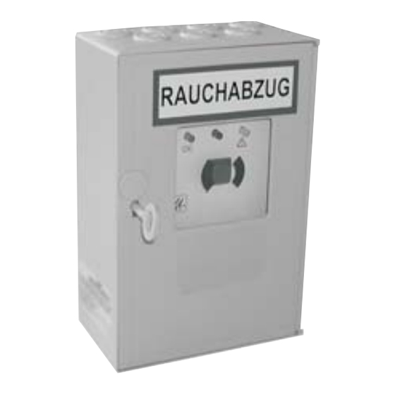
Während der Außerbetriebnahme stoppt der aktivierte Wartungstimer und speichert die letzten Daten. Sobald die Zentrale wieder an das Netz angeschlossen wird, läuft der Wartungstimer wie gewohnt weiter. Maße RAUCHABZUG TRZ Plus DG UP-Rahmen, optionales Zubehör für TRZ Plus DG 04/24999499... -
Page 21: Technische Daten
RWA Treppenraumzentrale TRZ Plus DG Technische Daten Die Energieversorgungen und elektrischen Steuereinrichtungen sind ausschließlich mit den vom Hersteller zugelassenen Komponenten zu betreiben. Elektrische Eigenschaften Primäre Energieversorgung Netzversorgungsspannung: 230 V AC / 50 Hz, (±10 %), separat abgesichert Systemspannung: 27 V DC (Nenn) (-25 % / +10 %) Leistungsaufnahme: max. - Page 22 RWA Treppenraumzentrale TRZ Plus DG Technische Daten Potenzialfreier Kontakt RWA-Auslösung und/oder Sammelstörung: Wechslerkontakt max. 30 V DC / 0,5 A Mechanische Eigenschaften Maße: siehe Seite 20 Gewicht: ca. 8 kg mit Akku, ca. 3 kg ohne Akku Anschluss und Betrieb...
- Page 23 RWA Treppenraumzentrale TRZ Plus DG Technische Daten Hinweispfl icht nach § 12 der Batterieverordnung (BattV) Im Zusammenhang mit dem Vertrieb von Batterien und Akkus sind wir als Händler gemäß Batterieverordnung verpfl ichtet, Sie als Verbraucher auf folgendes hinzuweisen: - Jeder Endverbraucher ist gesetzlich verpfl ichtet, Batterien und Akkus zurückzugeben! - Sie können diese nach Gebrauch in unseren Werken oder in einer kommunalen Sammelstelle zurück geben.
- Page 24 Start up procedure and trial run Troubleshooting Maintenance Out of order Measures Technical datas • • • • Herausgeber: STG-BEIKIRCH Industrieelektronik + Sicherheitstechnik GmbH & Co. KG Trifte 89 D-32657 Lemgo-Lieme info@STG-BEIKIRCH.de www.STG-BEIKIRCH.de Datei: Ti_TRZ_Plus_DG_D_GB_PL.indd / Ausgabe 04 / 02.01.2013 / Art.Nr. 24999499...
-
Page 25: Function
SHE control panel TRZ Plus DG SHE control panel TRZ Plus DG To connect 24 V DC pressurized gas generators Function Smoke protection control unit for pressurized gas generators, for the opening of smoke extraction covers in the case of fi re. -
Page 26: Safety Instructions
SHE control panel TRZ Plus DG Safety instructions Documentation: This documentation is exclusively valid Operation: Safe operation is guaranteed if the for the product or product range as stated in the type acceptable rated values and guidelines regarding designation on the cover and must be applied maintenance information stated in this documentation, as comprehensively. - Page 27 SHE control panel TRZ Plus DG Safety instructions Disposal: Packaging is to be disposed of Cabling for extra-low voltages (e.g. 24 V DC) is to be laid appropriately. Electrical equipment is to be separately from low-voltage line (e.g. 230 V AC).
-
Page 28: Possible Connections
SHE control panel TRZ Plus DG Possible connections • pressurized gas generator 24 V DC (max. 8 pieces connected in series; each 1.0 - 1.6 Ohm per piece) • 10 SHE manual call points RBH/3A... (line termination via enclosed end resistance), 1 SHE manual call point is integrated •... -
Page 29: Routing Of Cables
SHE control panel TRZ Plus DG Routing of cables Pressurized gas generator 24 V DC max. 8 pieces automatic alarm unit (last alarm unit with monitoring resistor) Cable type see table Observe VDE regulations! Siren 24 V AC / DC 100 mA IY (ST) Y 2 x 2 x 0.8 mm, max. -
Page 30: Integrated Trz Plus Dg Module
TRZ Plus DG module Sliding switch for “active”(ON) and “secured” (OFF) The extension by the additional TRZ Plus DG module, it is part of the TRZ Plus DG standard. The following components can be connected: 8 x pressurized gas generators 1 x pot.-free transmission Alarm (SHE-activation) or... -
Page 31: Connecting Diagram Mains
SHE control panel TRZ Plus DG Connecting diagram mains All work to be carried out without mains supply (230 V AC) or any batteries connected. Route the connecting cables into the control panel housing at the top. Connect all connecting cables according to the wiring diagram and make sure that they are correctly connected. -
Page 32: Connecting Diagram She Manual Call Point
SHE control panel TRZ Plus DG Connecting diagram SHE manual call point All work to be carried out without mains supply (230 V AC) or any batteries connected. Route the connecting cables into the control panel housing at the top. Connect all connecting cables according to the wiring diagram and make sure that they are correctly connected. -
Page 33: Connecting Diagram Smoke Detector
SHE control panel TRZ Plus DG Connecting diagram smoke detector All work to be carried out without mains supply (230 V AC) or any batteries connected. Route the connecting cables into the control panel housing at the top. Connect all connecting cables according to the wiring diagram and make sure that they are correctly connected. -
Page 34: Connecting Diagram Fire Alarm System
SHE control panel TRZ Plus DG Connecting diagram Fire Alarm System All work to be carried out without mains supply (230 V AC) or any batteries connected. Route the connecting cables into the control panel housing at the top. Connect all connecting cables according to the wiring diagram and make sure that they are correctly connected. -
Page 35: Connecting Buzzer / Signal Lamp
SHE control panel TRZ Plus DG Connecting buzzer / signal lamp All work to be carried out without mains supply (230 V AC) or any batteries connected. Route the connecting cables into the control panel housing at the top. Connect all connecting cables according to the wiring diagram and make sure that they are correctly connected. -
Page 36: Connecting Diagram Potential Free Contacts
SHE control panel TRZ Plus DG Connecting diagram potential free contacts All work to be carried out without mains supply (230 V AC) or any batteries connected. Route the connecting cables into the control panel housing at the top. Connect all connecting cables according to the wiring diagram and make sure that they are correctly connected. -
Page 37: Connection Diagram
SHE control panel TRZ Plus DG Connection diagram All work to be carried out without mains supply (230 V AC) or any batteries connected. Route the connecting cables into the control panel housing at the top. Connect all connecting cables according to the wiring diagram and make sure that they are correctly connected. -
Page 38: Function Of Dip-Switches
SHE control panel TRZ Plus DG Function of DIP-Switches Adjustable functions for ON setting DIP-Switch 4: “Fire Alarm System Open” and “Reset via 1 x Fire Alarm System closer contact” DIP-Switch 5: Pre-alert DIP-Switch 8: SHE Closed (on the SHE operating station) = SHE-Reset... -
Page 39: Service Port
OK indicating “unit functioning properly“ is not illuminated. On the TRZ Plus DG module the LED continues to fl ash, indicating “OFF“. Once the activation has been successfully completed, the slider switch must be switched to the “secured“ position. Press the CLOSED button on one of the SHE manual call points. - Page 40 fl ashes indicating “malfunction“ (fl ash code 5). On the TRZ Plus DG module the yellow LED fl ashes indicating “OFF“. Press the red ON button one of the SHE manual call points and the horn or indicator light connected to it will be triggered. The red LED indicator - SHE activated - illuminates at all SHE manual call points.
-
Page 41: Troubleshooting
The green LED - Operation OK - fl ashes steadily: Reset or setting of maintenance timer by confi guration-software of TRZ Plus DG. For more information please see technical information of PC Software Service Port of TRZ Plus DG. 04/24999499... -
Page 42: Maintenance
During the period out of operation the activated service timer stops and stores the last forwarded data. As soon as the control panel system is once again connected to the mains the service timer continues to run as usual. Measures SMOKE VENT TRZ Plus DG UP-frame, accessory optional for TRZ plus DG 04/24999499... -
Page 43: Technical Datas
SHE control panel TRZ Plus DG Technical datas The power supplies and electrical control equipment are to be operated exclusively with the components authorised by the manufacturer. Electrical properties Primary energy supply Operating voltage supply: 230 V AC / 50 Hz, (±10 %), separately fused... - Page 44 SHE control panel TRZ Plus DG Technical datas Potential-free contacts SHE activation and/or accumulative fault: changeover contact max. 30 V DC / 0.5 amp Mechanical properties Dimensions: see page 42 Weight: approx. 8 kg with battery, approx. 3 kg without battery...
- Page 45 SHE control panel TRZ Plus DG Technical datas Duty of information in accordance with § 12 of the EU battery directive: Relating to the sales of non-rechargeable and rechargeable batteries we as traders are obliged in accordance with the EU battery directive to inform you as consumers of the following: - Every end consumer is legally obliged to return non-rechargeable and rechargeable batteries! - These can be returned after use to our factories, or to a communal collection point.
- Page 46 Postępowanie w razie usterek Przeglądy i konserwacja Wyłączanie z użytkowania Wymiary Dane techniczne • • • • Herausgeber: STG-BEIKIRCH Industrieelektronik + Sicherheitstechnik GmbH & Co. KG Trifte 89 D-32657 Lemgo-Lieme info@STG-BEIKIRCH.de www.STG-BEIKIRCH.de Datei: Ti_TRZ_Plus_DG_D_GB_PL.indd / Ausgabe 04 / 02.01.2013 / Art.Nr. 24999499...
-
Page 47: Zastosowanie
Centrala oddymiania klatek schodowych TRZ Plus DG Centrala oddymiania klatek schodowych TRZ Plus DG Do podłączania do generatorów gazów sprężonych 24 V DC Zastosowanie Centrala oddymiania dla generatorów gazów sprężonych otwiera klapy pożarowe w razie pożaru. Z zamontowanym przełącznikiem suwakowym dla funkcji: „uzbrojona”... -
Page 48: Wskazówki Bezpieczeństwa
Centrala oddymiania klatek schodowych TRZ Plus DG Wskazówki bezpieczeństwa Dokumentacja: Niniejsza dokumentacja odnosi się podzespołów oraz udokumentować badania i ich wyniki. wyłącznie do produktu lub serii produktów zgodnych z oznaczeniem typu na stronie tytułowej i musi być Praca: Bezpieczną pracę zapewnia przestrzeganie stosowana w pełnym zakresie. - Page 49 Centrala oddymiania klatek schodowych TRZ Plus DG Wskazówki bezpieczeństwa Usuwanie: Opakowania należy usuwać Przewody napięcia bezpiecznego (np. 24 V DC) należy zgodnie z przepisami. Urządzenia elektryczne układać oddzielnie od przewodów niskonapięciowych (np. oddawać do punktów zbioru złomu elektrycznego i 230 V AC). Przewody wiotkie tak układać, aby podczas elektronicznego.
-
Page 50: Możliwości Podłączania
Centrala oddymiania klatek schodowych TRZ Plus DG Możliwości podłączania • generatory gazu sprężonego 24 V DC (max. 8 szt. w szeregu: rezystancja każdej sztuki 1,0 - 1,6 Ω) • 10 pulpitów sterowniczych oddymiania RBH/3A... (zamknięcie linii dołączonym rezystorem końcowym), 1 pulpit steroni czy oddymiania jest zintegrowany •... -
Page 51: Schemat Kabli
Centrala oddymiania klatek schodowych TRZ Plus DG Schemat kabli generator gazu sprężonego 24 V DC max. 8 szt. automatyczne czujniki (z rezystorem kontrolnym w ostatnim cokole czujnika) Typ kabla patrz tabela długości kabli! Przestrzegać przepisów VDE! Syrena V AC / DC 100 mA IY (ST) Y 2 x 2 x 0,8 mm, max. -
Page 52: Zintegrowane Moduł Trz Plus Dg
TRZ Plus DG Przełącznik suwakowy funkcji „uzbrojona” (ON) i „zabezpieczona” (OFF) Moduł TRZ Plus DG wchodzi w zakres dostawy centrali TRZ Plus DG. Można podłączyć następujące układy: 8 x generatorów gazu sprężonego 1 x bezpotencjałowe wyprowadzenie alarmu (zadziałanie oddymiania) albo 1 x bezpotencjałowe wyprowadzenie sygnału zbiorczego usterki, obciążenie styków max. -
Page 53: Podłączanie Do Sieci
Centrala oddymiania klatek schodowych TRZ Plus DG Podłączenie do sieci Wszystkie prace wykonywać bez podłączonego napięcia sieciowego (230 V AC) i bez podłączonych akumulatorów/ baterii. Przewody przyłączeniowe wprowadzić od góry do obudowy centrali sterowania. Podłączać przewody przyłączeniowe według schematu zacisków, uważając na prawidłowe podłączanie. Nieprawidłowe podłączenie do zacisku albo pomylenie numeru lub koloru może spowodować... -
Page 54: Podłączanie Pulpitu Sterowniczego Oddymiania
Centrala oddymiania klatek schodowych TRZ Plus DG Podłączanie pulpitu sterowniczego oddymiania Wszystkie prace wykonywać bez podłączonego napięcia sieciowego (230 V AC) i bez podłączonych akumulatorów. Przewody przyłączeniowe wprowadzić od góry do obudowy centrali sterowania. Podłączać przewody przyłączeniowe według schematu zacisków, uważając na prawidłowe podłączanie. Nieprawidłowe podłączenie do zacisku albo pomylenie numeru lub koloru może spowodować... -
Page 55: Podłączenie Automatycznych Czujników
Centrala oddymiania klatek schodowych TRZ Plus DG Podłączenie automatycznych czujników Wszystkie prace wykonywać bez podłączonego napięcia sieciowego (230 V AC) i bez podłączonych akumulatorów. Przewody przyłączeniowe wprowadzić od góry do obudowy centrali sterowania. Podłączać przewody przyłączeniowe według schematu zacisków, uważając na prawidłowe podłączanie. Nieprawidłowe podłączenie do zacisku albo pomylenie numeru lub koloru może spowodować... -
Page 56: Podłączanie Sygnalizacji Pożarowej
Centrala oddymiania klatek schodowych TRZ Plus DG Podłączanie sygnalizacji pożarowej Wszystkie prace wykonywać bez podłączonego napięcia sieciowego (230 V AC) i bez podłączonych akumulatorów. Przewody przyłączeniowe wprowadzić od góry do obudowy centrali sterowania. Podłączać przewody przyłączeniowe według schematu zacisków, uważając na prawidłowe podłączanie. Nieprawidłowe podłączenie do zacisku albo pomylenie numeru lub koloru może spowodować... -
Page 57: Podłączanie Sygnału Dźwiękowego/Świetlnego
Centrala oddymiania klatek schodowych TRZ Plus DG Podłączanie sygnału dźwiękowego/świetlnego Wszystkie prace wykonywać bez podłączonego napięcia sieciowego (230 V AC) i bez podłączonych akumulatorów. Przewody przyłączeniowe wprowadzić od góry do obudowy centrali sterowania. Podłączać przewody przyłączeniowe według schematu zacisków, uważając na prawidłowe podłączanie. Nieprawidłowe podłączenie do zacisku albo pomylenie numeru lub koloru może spowodować... -
Page 58: Podłączanie Zestyków Bezpotencjałowych
Centrala oddymiania klatek schodowych TRZ Plus DG Podłączanie zestyków bezpotencjałowych Wszystkie prace wykonywać bez podłączonego napięcia sieciowego (230 V AC) i bez podłączonych akumulatorów. Przewody przyłączeniowe wprowadzić od góry do obudowy centrali sterowania. Podłączać przewody przyłączeniowe według schematu zacisków, uważając na prawidłowe podłączanie. Nieprawidłowe podłączenie do zacisku albo pomylenie numeru lub koloru może spowodować... -
Page 59: Przegląd Podłączeń
Centrala oddymiania klatek schodowych TRZ Plus DG Przegląd podłączeń Wszystkie prace wykonywać bez podłączonego napięcia sieciowego (230 V AC) i bez podłączonych akumulatorów. Przewody przyłączeniowe wprowadzić od góry do obudowy centrali sterowania. Podłączać przewody przyłączeniowe według schematu zacisków, uważając na prawidłowe podłączanie. Nieprawidłowe podłączenie do zacisku albo pomylenie numeru lub koloru może spowodować... -
Page 60: Funkcje Przełączników Dwupołozeniowych Dip
Centrala oddymiania klatek schodowych TRZ Plus DG Funkcje przełączników dwupołożeniowych DIP Funkcje do ustawiania w pozycji ON (włączony) Przełącznik DIP 4: „oddymianie otwarte“ i „Reset przez 1 x zestyk zwierny oddymiania“ Przełącznik DIP 5: alarm wstępny czujnika 1 2 3 4 5 6 7 8 9 101112 Przełącznik DIP... -
Page 61: Service Port
„zadziałanie oddymiania“ świeci, zielony wskaźnik diodowy - praca OK - nie świeci. Na module TRZ Plus DG nadal miga dioda świecąca „OFF“. Po zadziałaniu należy przestawić przełącznk suwakowy do położenia „zabezpieczone“. Wcisnąć przycisk zamykania ZU na którymś pulpicie sterowniczym oddymiania. - Page 62 Wcisnąć przycisk resetu oddymiania (RWA Reset) na centrali sterowania (na panelu). Czerwony wskaźnik na automatycznym czujniku gaśnie. Żółty wskaźnik diodowy - usterka - (kod migowy 5) miga. Na module TRZ Plus DG miga teraz żółty wskaźnik diodowy wyłączenia „OFF“. Następnie przestawić przełącznik suwakowy w centrali do położenia „uzbrojona”.
-
Page 63: Postępowanie W Razie Usterek
Przegląd Zielony wskaźnik diodowy - praca OK - miga równomiernie: Resetowanie lub ustawianie zegara sygnalizującego przeglądy przez oprogramowanie konfi guracyjne TRZ Plus DG. Dalsze informacje patrz informacja techniczna o oprogramowaniu dla komputera PC Service Port dla TRZ Plus DG. 04/24999499... -
Page 64: Przeglądy I Konserwacja
Podczas wyłączenia z użytkowania włączony licznik czasu do przeglądu jest zatrzymany i zapisuje w pamięci ostatnie dane. Z chwilą ponownego podłączenia centrali so sieci licznik czasu pracuje dalej jak poprzednio. Wymiary ODDYMIANIE TRZ Plus DG Rama do montażu podtynkowego, wyposażenie w opcji dla TRZ Plus DG 04/24999499... -
Page 65: Dane Techniczne
Centrala oddymiania klatek schodowych TRZ Plus DG Dane techniczne Układy zasilania energią i elektryczne urządzenia sterujące mogą być użytkowane wyłącznie z podzespołami dopuszczonymi przez producenta. Parametry elektryczne Główne zasilanie energią Napięcie sieci zasilającej: 230 V AC / 50 Hz, (±10 %), z oddzielnymi bezpiecznikami Napięcie instalacji:... - Page 66 Centrala oddymiania klatek schodowych TRZ Plus DG Dane techniczne Zestyki bezpotencjałowe Zadziałanie oddymiania oraz/lub Zbiorczy sygnał usterki: zmieniacz kontakt maksymalny 30 V DC / 0,5 A Parametry mechaniczne Wymiary: patrz strona 64 Ciężar: ok. 8 kg z akumulatorami, ok. 3 kg bez akumulatora Podłączenie i praca...
- Page 67 Centrala oddymiania klatek schodowych TRZ Plus DG Dane techniczne Obowiązek informowania w myśl § 12 Rozporządzenia o bateriach (BattV) W związku ze sprzedażą przez nas baterii i akumulatorów jesteśmy, na mocy Rozporządzenia o bateriach, zobowiązani poinformować użytkownika o następujących kwestiach: - Na każdym końcowym użytkowniku spoczywa ustawowy obowiązek zwrotu baterii i akumulatorów!
Need help?
Do you have a question about the TRZ Plus DG and is the answer not in the manual?
Questions and answers