Chapters
Table of Contents

Related Manuals for STG-BEIKIRCH 4A


Summary of Contents for STG-BEIKIRCH 4A
- Page 1 RWA Kompaktzentrale 4A, 4A/M und 8A, 8A/M Technische Information und Bedienungsanleitung Compact control panel 4A, 4A/M and 8A, 8A/M Technical information and operating instruction...
-
Page 2: Table Of Contents
Service Port Inbetriebnahme und Probelauf Störungshilfe Wartung Außer Betrieb Maßzeichnung Technische Daten • • • • Herausgeber: STG-BEIKIRCH Industrieelektronik + Sicherheitstechnik GmbH & Co. KG Trifte 89 D-32657 Lemgo info@STG-BEIKIRCH.de www.STG-BEIKIRCH.de Datei: Ti_Kompaktzentrale_4A_8A_D_GB.indd / Ausgabe 08 / 22.06.2017 / Art.Nr. 13424999756... -
Page 3: Geräteübersicht, Lieferumfang
RWA Kompaktzentrale 4A, 4A/M und 8A, 8A/M RWA Kompaktzentrale 4A, 4A/M und 8A, 8A/M Zur Ansteuerung von 24 V DC Linear- und Kettenantrieben für Rauchabzug und tägliche Lüftung. Geräteübersicht • Funktion “Tägliches Lüften” • eine RWA-Gruppe (RG) und zwei Lüftungsgruppen (LG) •... -
Page 4: Sicherheitshinweise
RWA Kompaktzentrale 4A, 4A/M und 8A, 8A/M Sicherheitshinweise Dokumentation: Diese Dokumentation gilt ausschließ- der Installation sind die elektrischen und mechanischen lich für das Produkt oder die Produktserie gemäß der Komponenten auf einwandfreie Funktion zu prüfen und Typenbezeichung des Deckblattes und muss im vollen die Prüfungen und ihre Ergebnisse zu dokumentieren. - Page 5 RWA Kompaktzentrale 4A, 4A/M und 8A, 8A/M Sicherheitshinweise Entsorgung: Verpackungen sind sachgerecht zu Leitungen für Kleinspannungen (z. B. 24 V DC) sind entsorgen. Die elektrischen Geräte sind an Sam- getrennt von Niederspannungsleitungen (z. B. 230 V AC) melstellen für die Rücknahme von Elektro- und Elektro- zu verlegen.
-
Page 6: Kabellängendiagramm
RWA Kompaktzentrale 4A, 4A/M und 8A, 8A/M Kabellängendiagramm Kabellängendiagramm zur Ermittlung der notwendigen Kabelquerschnitte in Abhängigkeit der Leitungslänge und der Summe der Nennströme der Antriebe. Kabellängendiagramm bis 8 Ampere für Antriebe Kabellängendiagramm bis 8 Ampere für Antriebe mit einer Stromaufnahme < 2,5 A... -
Page 7: Auswahl Der Leitungen
RWA Kompaktzentrale 4A, 4A/M und 8A, 8A/M Auswahl der Leitungen Hinweis: Für die Motorzuleitungen von RWA Antrieben werden 3 bzw. 5 Einzeladern (doppelt aufgelegt) benötigt. Zwei Adern (4 Adern) sind für die Motorspannung, die 3. bzw. 5. Ader wird für die Überwachung der Leitung benötigt. -
Page 8: Montage
RWA Kompaktzentrale 4A, 4A/M und 8A, 8A/M Montage Hinweis: Alle hier aufgeführten Zentralen sind ausschließlich für eine Wandbefestigung geeignet. Die Akkus befinden sich unten und müssen auf dem Gehäuseboden aufliegen. Wandbefestigung Kompaktzentrale 4A, 8A: Befestigungsbohrung Zuerst Grundplatte mit Steuerelektronik ausbauen. Gehäuse gemäß Befestigungsbohrungen mit geeigneten Dübel und Schrauben an der Wand befestigen. - Page 9 RWA Kompaktzentrale 4A, 4A/M und 8A, 8A/M Montage Montage Kompaktzentrale 4A/M Nachdem das Gehäuse an der Wand befestigt wurde: Klettbänder zur Akkubefestigung in die Montageplatte einfädeln. Erdungsanschluss nicht vergessen: Es ist sicherzustellen, dass die Platine mit dem Gehäuse geerdet ist.
- Page 10 RWA Kompaktzentrale 4A, 4A/M und 8A, 8A/M Montage Einsetzen der Akkus Mithilfe der Klettbänder C (im unteren Teil der Grundplatte) die Akkus auf der Unterseite der Zentrale befestigen. Bei der Kompaktzentrale 8A/M werden zur Akkubefestigung Metallbügel verwendet. Die Akkus nach unten stehendem Anschlussschema brücken und verbinden.
-
Page 11: Kabelplan
RWA Kompaktzentrale 4A, 4A/M und 8A, 8A/M Kabelplan e M9 . 1 A Beispielantriebe Linearantriebe M9 x. 1 amp 24 V DC, max. 1 A (mit eingebauter Lastabschaltung) Wind-/Regenmelder 24 V AC / DC 100 mA Wind motor units Motorkreis (MK) 2... -
Page 12: Anschlussmöglichkeiten
RWA Kompaktzentrale 4A, 4A/M und 8A, 8A/M Anschlussmöglichkeiten • 24 V DC Antriebe mit eigener Abschaltung (Lastabschaltung, Endschalter) • gesamte Stromaufnahme aller angeschlossenen Antriebe max. 4 A bzw. 8 A je nach Zentralentyp • 10 RWA-Bedienstellen RBH/3A... (Linienabschluss über beiliegenden Endwiderstand) •... -
Page 13: Anschlussübersicht
RWA Kompaktzentrale 4A, 4A/M und 8A, 8A/M Anschlussübersicht Alle Arbeiten sind ohne Netzanschluss (230 V AC) und ohne angeschlossene Akkus durchzuführen. Alle Anschluss- leitungen sind von oben in das Gehäuse der Steuerzentrale zu führen. Die Anschlussleitungen sind nach Klemmplan anzuklemmen. Hierbei muss immer auf den richtigen Anschluss geachtet werden. Falsches Anklemmen sowie Num- mern- oder Farbendreher können zu Fehlfunktionen der Steuerzentrale oder der externen Elemente führen. -
Page 14: Anschluss Antriebe
RWA Kompaktzentrale 4A, 4A/M und 8A, 8A/M Anschluss Antriebe ein Antrieb MK1 oder mehrere Antriebe keine Antriebe am je Motorkreis je Motorkreis Motorkreis 1 oder 2 MK 1 MK 2 MK 1 MK 2 nicht belegt Abzweigdose Abzweigdose letzter Antrieb... -
Page 15: Anschluss Haftmagnete / Magnetverriegelung
RWA Kompaktzentrale 4A, 4A/M und 8A, 8A/M Anschluss Haftmagnete / Magnetverriegelung Alle Arbeiten sind ohne Netzanschluss (230 V AC) und ohne angeschlossene Akkus durchzuführen. Alle Anschlusslei- tungen sind von oben in das Gehäuse der Steuerzentrale zu führen. Die Anschlussleitungen sind nach Klemmplan an- zuklemmen. -
Page 16: Anschluss Automatischer Melder
RWA Kompaktzentrale 4A, 4A/M und 8A, 8A/M Anschluss automatischer Melder Alle Arbeiten sind ohne Netzanschluss (230 V AC) und ohne angeschlossene Akkus durchzuführen. Alle Anschlusslei- tungen sind von oben in das Gehäuse der Steuerzentrale zu führen. Die Anschlussleitungen sind nach Klemmplan an- zuklemmen. -
Page 17: Anschluss Brandmeldeanlage
RWA Kompaktzentrale 4A, 4A/M und 8A, 8A/M Anschluss Brandmeldeanlage Alle Arbeiten sind ohne Netzanschluss (230 V AC) und ohne angeschlossene Akkus durchzuführen. Alle Anschlusslei- tungen sind von oben in das Gehäuse der Steuerzentrale zu führen. Die Anschlussleitungen sind nach Klemmplan an- zuklemmen. -
Page 18: Anschluss Rwa-Bedienstelle
RWA Kompaktzentrale 4A, 4A/M und 8A, 8A/M Anschluss RWA-Bedienstelle Alle Arbeiten sind ohne Netzanschluss (230 V AC) und ohne angeschlossene Akkus durchzuführen. Alle Anschlusslei- tungen sind von oben in das Gehäuse der Steuerzentrale zu führen. Die Anschlussleitungen sind nach Klemmplan an- zuklemmen. -
Page 19: Anschluss Lüftungstaster
RWA Kompaktzentrale 4A, 4A/M und 8A, 8A/M Anschluss Lüftungstaster Alle Arbeiten sind ohne Netzanschluss (230 V AC) und ohne angeschlossene Akkus durchzuführen. Alle Anschlusslei- tungen sind von oben in das Gehäuse der Steuerzentrale zu führen. Die Anschlussleitungen sind nach Klemmplan an- zuklemmen. -
Page 20: Anschluss Wind-/Regenmelder
RWA Kompaktzentrale 4A, 4A/M und 8A, 8A/M Anschluss Wind-/Regenmelder Alle Arbeiten sind ohne Netzanschluss (230 V AC) und ohne angeschlossene Akkus durchzuführen. Alle Anschlusslei- tungen sind von oben in das Gehäuse der Steuerzentrale zu führen. Die Anschlussleitungen sind nach Klemmplan an- zuklemmen. -
Page 21: Anschluss Potenzialfreier Kontakte
RWA Kompaktzentrale 4A, 4A/M und 8A, 8A/M Anschluss potenzialfreier Kontakte Alle Arbeiten sind ohne Netzanschluss (230 V AC) und ohne angeschlossene Akkus durchzuführen. Alle Anschlusslei- tungen sind von oben in das Gehäuse der Steuerzentrale zu führen. Die Anschlussleitungen sind nach Klemmplan an- zuklemmen. -
Page 22: Anschluss Slave-Zentrale (Kaskadierfunktion)
RWA Kompaktzentrale 4A, 4A/M und 8A, 8A/M Anschluss Slave-Zentralen (Kaskadierfunktion) (ab Hardwareversion Rev019, Softwareversion V020001, siehe Kennzeichnung auf der Platine) Alle Arbeiten sind ohne Netzanschluss (230 V AC) und ohne angeschlossene Akkus durchzuführen. Alle Anschlusslei- tungen sind von oben in das Gehäuse der Steuerzentrale zu führen. Die Anschlussleitungen sind nach Klemmplan an- zuklemmen. - Page 23 RWA Kompaktzentrale 4A, 4A/M und 8A, 8A/M Anschluss Slave-Zentralen (Kaskadierfunktion) (ab Hardwareversion Rev019, Softwareversion V020001, siehe Kennzeichnung auf der Platine) Alle Arbeiten sind ohne Netzanschluss (230 V AC) und ohne angeschlossene Akkus durchzuführen. Alle Anschlusslei- tungen sind von oben in das Gehäuse der Steuerzentrale zu führen. Die Anschlussleitungen sind nach Klemmplan an- zuklemmen.
-
Page 24: Funktionsbeschreibung
RWA Kompaktzentrale 4A, 4A/M und 8A, 8A/M Funktionsbeschreibung Manuelle Auslösung bei Feuer/Brand/Alarm Rauchabzug / Fenster öffnen rote AUF-Taste in einer RWA-Bedienstelle drücken, Fenster werden vollständig geöffnet, rote LED-Anzeige RWA ausgelöst - leuchtet in allen RWA-Bedienstellen, die Lüftungsfunktion ist außer Betrieb. - Page 25 RWA Kompaktzentrale 4A, 4A/M und 8A, 8A/M Funktionsbeschreibung Hubbegrenzung (über Laufzeit) Die Hinweise auf Seite 28 sind zu beachten, DIP-Schalter 6 auf ON. Einlernen Die Fenster schließen! Die Tasten Auf und ZU (STOP) am Lüftungstaster drücken und solange gedrückt halten bis ein schnelles Blinken der AUF-Anzeige erscheint.
- Page 26 RWA Kompaktzentrale 4A, 4A/M und 8A, 8A/M Funktionsbeschreibung Master - Slave Funktion (ab Hardwareversion Rev019, Softwareversion V020001, siehe Kennzeichnung auf der Platine) Die Leitungen zur Kaskadierung werden auf Drahtbruch und Falschanschluss überwacht (siehe Kapitel Störungshilfe). Störungssignale werden von jeder Slavezentrale bis zur Masterzentrale weitergeleitet. Die Überwachungsfunktion ist an jeder Zentrale gewährleistet.
-
Page 27: Dip-Schalter Funktionen
RWA Kompaktzentrale 4A, 4A/M und 8A, 8A/M DIP-Schalter Funktionen Werkseitig befinden sich alle DIP-Schalter in Stellung OFF (Aus). Einstellbare Funktionen bei Stellung ON (EIN) DIP-Schalter DIP-Schalter 1: Ausschalten der Motortaktung (VdS Funktion) DIP-Schalter 2: Motorausgang dauerhaft eingeschaltet DIP-Schalter 3: Funktion Türfeststellzentrale mit Haftmagneten oder Magnetverriegelungen DIP-Schalter 4: “BMA Auf“ und "Reset über 1x BMA-Schließerkontakt"... - Page 28 RWA Kompaktzentrale 4A, 4A/M und 8A, 8A/M DIP-Schalter Funktionen DIP-Schalter 5: “BMA Auf“ über einen Öffnerkontakt (nur für Kompaktzentrale 8A) Anschluss über die Klemmen der automatischen Melder mit Zusatzmodul UEB3-1K. BMA-Kontakt geschlossen = Stand- by Betrieb, BMA-Kontakt geöffnet = RWA. Nach einer Auslösung ist ein Reset mit dem Resettaster auf der Grundplatine der Zentrale auszuführen.
- Page 29 RWA Kompaktzentrale 4A, 4A/M und 8A, 8A/M DIP-Schalter Funktionen Folgende Schalterkombinationen ergeben Sonderfunktionen: 1. DIP-Schalter 2 + 3 = ON (Kombinationen mit DIP-Schalter 4, 5, 7-12 weiterhin möglich). Funktion: • Die Lüftungstastereingänge sind ohne Funktion. • Keine Motortaktung (bei RWA über 30 Minuten, VdS Funktion).
-
Page 30: Service Port
PC Softwareversion und der Firmware der Zentrale. Der Wartungstimer kann ausschließlich über die Software zurückgesetzt werden. Zur Änderung einer Konfiguration über die Service-Port-Schnittstelle muss das Service-Port-Verbindungskabel mit der RWA-Steuerzentrale Typ Kompaktzentrale 4A, 4A/M, 8A, 8A/M und dem PC verbunden werden. Voraussetzung zur Konfiguration ist die funktionsfähige Installation der Service-Port-Software, ggf. müssen zusätzliche notwendigen Trei- berdateien für das Verbindungskabel verwendet werden. Siehe entsprechende Installationshinweise zur Software. Die RWA-Steuerzentrale ist während der Konfiguration mit Netzspannung zu versorgen. - Page 31 RWA Kompaktzentrale 4A, 4A/M und 8A, 8A/M Service Port Software Nach Auslesen der Daten der Kompaktzentrale wird zusätzlich die Information angezeigt, ob ein interner Fehler vorliegt oder nicht. Es besteht die Möglichkeit die Konfiguration als Datei auf einer Festplatte zu speichern. Hierfür ist der Menüpunkt „Datei“ > „Konfiguration speichern“ auszuwählen.
- Page 32 RWA Kompaktzentrale 4A, 4A/M und 8A, 8A/M Service Port Software 2.2 Max. Öffnungsweite bei Lüftung Diese Funktion dient dazu eine Hubbegrenzung durch eine Laufzeit (in Sekunden) zu realisieren. Hierbei entspricht der maximale Hub [mm] 200 Sekunden, der Null Hub [mm] (nicht ausgefahren) 0 Sekunden.
-
Page 33: Inbetriebnahme Und Probelauf
RWA Kompaktzentrale 4A, 4A/M und 8A, 8A/M Inbetriebnahme und Probelauf Hinweis: Die Angaben zur Inbetriebnahme beziehen sich auf die Standardfunktionen. Alle DIP-Schalter befinden sich in Stellung OFF (Aus). Hinweis: Vor Inbetriebnahme prüfen, ob die Akkus ausreichend fest durch die Klettbänder oder Haltebügel fixiert sind. Ein Betrieb ohne Akkubefestigung ist nicht zulässig! Ohne Netzspannung, ohne Akku Alle Teile mechanisch und elektrisch auf feste Verschraubung und auf Beschädigungen prüfen, die Klemmen:... - Page 34 RWA Kompaktzentrale 4A, 4A/M und 8A, 8A/M Inbetriebnahme und Probelauf RWA-Bedienstellen Taste RWA-AUF kurz betätigen, die Fenster öffnen vollständig. Die rote LED-Anzeige - RWA ausgelöst - leuchtet. Die grüne LED-Anzeige - Betrieb OK - leuchtet. Das akustische Dauersignal ertönt (nur bei RWA-Bedienstelle mit eingebautem Summer und gedrücktem Türkontaktschalter).
- Page 35 RWA Kompaktzentrale 4A, 4A/M und 8A, 8A/M Inbetriebnahme und Probelauf Abschließende Arbeiten Einschlagscheiben in allen RWA-Bedienstellen einsetzen. Tür der Steuerzentrale schließen. Telefonnummer des Störungsdienstes aufkleben. Achtung: Wenn der Probelauf fehlschlägt, Inbetriebnahme wiederholen! Störungshilfe Anzeige - Betrieb OK - leuchtet nicht in den RWA-Bedienstellen sowie Steuerzentrale: •...
-
Page 36: Störungshilfe
Das UEB2-Modul ist falsch angeschlossen. Fehleranzeige nur an der Slave-Zentrale, die den Fehler ausgelöst hat. Wartungsanzeige (gleichmäßiges Blinken) Wartung Grüne LED - Betrieb OK - blinkt schnell: Reset bzw. Setzen des Wartungstimers über die Konfigurations- software zur Kompaktzentrale 4A und 8A. Weitere Informationen siehe technische Informationen zur PC Software Service Port zur Kompaktzentrale 4A und 8A. Wind-/oder Regenmeldung (gleichmäßiges Blinken) Leuchtanzeige im Lüftungstaster LTA 25. Auf-Anzeige (Dauersignal) __________________________ Leuchtanzeige im Lüftungstaster LTA 25. -
Page 37: Wartung
RWA Kompaktzentrale 4A, 4A/M und 8A, 8A/M Wartung Werden die Geräte in Rauch- und Wärmeabzugsanlagen (kurz RWA) eingesetzt, müssen sie mindestens einmal jährlich geprüft, gewartet und ggf. instand gesetzt werden. Bei reinen Lüftungsanlagen ist dies auch zu empfehlen. Die Geräte von Verunreinigungen befreien. Befestigungs- und Klemmschrauben auf festen Sitz prüfen. Die Geräte durch Probelauf testen, gemäß... -
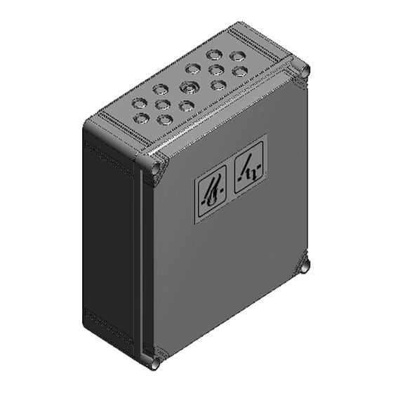
Page 38: Maßzeichnung
RWA Kompaktzentrale 4A, 4A/M und 8A, 8A/M Maßzeichnung Kompaktzentrale 4A , 8A Kompaktzentrale 4A Kompaktzentrale 8A (mit Zwischenrahmen) Kompaktzentrale 4A/M (Metallgehäuse) Kompaktzentrale 8A/M (Metallgehäuse) 08/13424999756... -
Page 39: Technische Daten
Haftmagnete: <1 % Strom (Nenn): Antriebe: Typ 4A: 4 A bei 30 % ED* / Typ 8A: 8 A bei 30 % ED* Ausgang separat abgesichert, Haftmagnete: Typ 4A: 1 A bei 100 % ED* / Typ 8A: 2A bei 100 % ED* * Bezugnehmend auf 10 min Öffnungs- /Schließvorgang:... - Page 40 Seite 38 Gewicht: Typ 4A: mit Akku ca. 6 kg, ohne Akku ca. 4 kg Typ 4A/M: mit Akku ca. 6 kg, ohne Akku ca. 4 kg Typ 8A: mit Akku ca. 6,5 kg, ohne Akku ca. 4,5 kg Typ 8A/M: mit Akku ca.
- Page 41 Geeignet für Außenmontage: nein Schutzart IP: Kunststoffgehäuse 4A und 8A: IP 44 nach DIN EN 60529 Metallgehäuse 4A/M: IP 20 nach DIN EN 60529, IP30 im angebauten Zustand Metallgehäuse 8A/M: IP 42 nach DIN EN 60529 Zulassungen und Nachweise CE konform: gemäß...
-
Page 42: Datei: Ti_Kompaktzentrale_4A_8A_D_Gb.indd / Ausgabe 08 / 22.06.2017 / Art.nr
Compact control panel 4A, 4A/M und 8A, 8A/M Contents Page Equipment overview scope of delivery Safety instructions Cable length diagram Cable cross-section determination Selecting the cables Assembly Routing of cables Connection facilities Connection overview Connection to mains (230 V) Connection to drives... -
Page 43: Equipment Overview
Compact control panel 4A, 4A/M und 8A, 8A/M Compact control panel 4A, 4A/M and 8A, 8A/M To control 24 V DC linear and chain drives for smoke extraction and natural ventilation. Equipment overview • function “daily ventilation” • one SHE group and two ventilstion groups •... -
Page 44: Safety Instructions
Compact control panel 4A, 4A/M und 8A, 8A/M Safety instructions Documentation: This documentation is exclusively valid Operation: Safe operation is guaranteed if the accepta- for the product or product range as stated in the type ble rated values and guidelines regarding maintenance... - Page 45 Compact control panel 4A, 4A/M und 8A, 8A/M Safety instructions Disposal: Packaging is to be disposed of appropriately. Electrical equipment is to be dis- Cabling for extra-low voltages (e.g. 24 V DC) is to be laid posed of at recycling collection points for scrap electrical separately from low-voltage line (e.g.
-
Page 46: Cable Length Diagram
Compact control panel 4A, 4A/M und 8A, 8A/M Cable length diagram To determine the necessary cable cross-sections as a function of the line length and the sum of the rated currents of the drives. Cable length diagram up to 8 amperes Cable length diagram up to 8 amperes for drives with a power consumption <... -
Page 47: Selecting The Cables
Compact control panel 4A, 4A/M und 8A, 8A/M Selecting the cables Note: For the motor supply cables of SHE drives 3 or 5 (duplicated layout) individual cores are required. Two cores (4 cores) are for the motor voltage, the 3rd or 5th core respectively is required for monitoring the cabling. The se- lection and layout of the cables is to be performed according to (model) utility facilities guidelines (MLAR). -
Page 48: Assembly
Compact control panel 4A, 4A/M und 8A, 8A/M Assembly Note: All listed Compact control paneles are only suitable for wall mounting. The batteries are located on the bottom and have to the case back rest. mounting hole Wall mounting Compact control panel 4A, 8A: First dismantle the baseplate with control electronics. - Page 49 Compact control panel 4A, 4A/M und 8A, 8A/M Assembly Assembly of compact control panel 4A/M Once the housing has been fastened to the wall: Thread velcro tapes for attaching the rechargeable batteries into the assembly panel. Earth connection not forgotten: It is ensure that the plate with the Housing is grounded.
- Page 50 Compact control panel 4A, 4A/M und 8A, 8A/M Assembly Inserting the rechargeable batteries With the help of the velcro tapes C (in the bottom part of the baseplate), fasten the rechargeable batteries on the underside of the control panel. In case of the compact control panel 8A/M the battery mounting is used of metal bracket.
-
Page 51: Routing Of Cables
Compact control panel 4A, 4A/M und 8A, 8A/M Routing of cables rantriebe M9 DC, max. 1 A ingebauter bschaltung) Example motor units r drives M9 Linear drives M9 DC, max. 1 amp 24V DC, max. 1 integrated amp (with integra-... -
Page 52: Connection Facilities
Compact control panel 4A, 4A/M und 8A, 8A/M Connection facilities • 24 V DC drives with separate cutoff (load interruption, limit switch) • total power consumption of all connected drives max. 4 A or 8 A depending on type of control panel •... -
Page 53: Connection Overview
Compact control panel 4A, 4A/M und 8A, 8A/M Connection overview All work must be carried out without mains connection (230 V AC) and without the batteries connected. Route all connec- tion cables into the control panel housing from the top. The connection cables must be connected according to the wiring diagram. It must be ensured that they are always connected correctly. Incorrect connections or figure or colour mix-ups... -
Page 54: Connection To Drives
Compact control panel 4A, 4A/M und 8A, 8A/M Connection to drives one drive per motor MK1 or several drives no drives at circuit per motor circuit motor circuit 1 or 2 MK 1 MK 2 MK 1 MK 2 not assigned... -
Page 55: Connecting Diagram Magnetic Clamps / Magnetic Locking
Compact control panel 4A, 4A/M und 8A, 8A/M Connecting diagram magnetic clamps / magnetic locking All work to be carried out without mains supply (230 V AC) or any batteries connected. Route the connecting cables into the control panel housing at the top. Connect all connecting cables according to the wiring diagram and make sure that they are correctly connected. Incorrect connections or figure or colour mix-ups can lead to incorrect function of the con-... -
Page 56: Connecting Diagram Smoke Detector
Compact control panel 4A, 4A/M und 8A, 8A/M Connecting diagram smoke detector All work to be carried out without mains supply (230 V AC) or any batteries connected. Route the connecting cables into the control panel housing at the top. Connect all connecting cables according to the wiring diagram and make sure that they are correctly connected. Incorrect connections or figure or colour mix-ups can lead to incorrect function of the con-... -
Page 57: Connecting Diagram Fire Alarm System
Compact control panel 4A, 4A/M und 8A, 8A/M Connecting diagram Fire Alarm System All work to be carried out without mains supply (230 V AC) or any batteries connected. Route the connecting cables into the control panel housing at the top. Connect all connecting cables according to the wiring diagram and make sure that they are correctly connected. Incorrect connections or figure or colour mix-ups can lead to incorrect function of the con-... -
Page 58: Connecting Diagram She Manual Call Point
Compact control panel 4A, 4A/M und 8A, 8A/M Connecting diagram SHE manuel call point All work to be carried out without mains supply (230 V AC) or any batteries connected. Route the connecting cables into the control panel housing at the top. Connect all connecting cables according to the wiring diagram and make sure that they are correctly connected. Incorrect connections or figure or colour mix-ups can lead to incorrect function of the con-... -
Page 59: Connecting Diagram Vent Switch
Compact control panel 4A, 4A/M und 8A, 8A/M Connecting diagram vent switch All work to be carried out without mains supply (230 V AC) or any batteries connected. Route the connecting cables into the control panel housing at the top. Connect all connecting cables according to the wiring diagram and make sure that they are correctly connected. Incorrect connections or figure or colour mix-ups can lead to incorrect function of the con-... -
Page 60: Connecting Diagram Wind/Rain Detector
Compact control panel 4A, 4A/M und 8A, 8A/M Connecting diagram wind/rain detector All work to be carried out without mains supply (230 V AC) or any batteries connected. Route the connecting cables into the control panel housing at the top. Connect all connecting cables according to the wiring diagram and make sure that they are correctly connected. Incorrect connections or figure or colour mix-ups can lead to incorrect function of the con-... -
Page 61: Connecting Potential-Free Contacts
Compact control panel 4A, 4A/M und 8A, 8A/M Connecting potential-free contacts All work to be carried out without mains supply (230 V AC) or any batteries connected. Route the connecting cables into the control panel housing at the top. Connect all connecting cables according to the wiring diagram and make sure that they are correctly connected. Incorrected connections or figure or colour mix-ups can lead to incorrect function of... -
Page 62: Connecting Control Panel Slave (Cascade Function)
Compact control panel 4A, 4A/M und 8A, 8A/M Connecting control panel Slave (Cascade function) (Rev019 hardware version, software version V020001, see marking on the board) All work to be carried out without mains supply (230 V AC) or any batteries connected. Route the connecting cables into the control panel housing at the top. - Page 63 Compact control panel 4A, 4A/M und 8A, 8A/M Connecting control panel Slave (Cascade function) (Rev019 hardware version, software version V020001, see marking on the board) All work to be carried out without mains supply (230 V AC) or any batteries connected. Route the connecting cables into the control panel housing at the top.
-
Page 64: Description Of Operating
Compact control panel 4A, 4A/M und 8A, 8A/M Description of operating Manual activation in case of fire/smoke/alarm Smoke heat extraction / opening windows Press the red OPEN switch at a SHE manual call point, the windows open completely, the red LED display - SHE activated - is shining at all SHE manual call points, the ventilation function is out of order. - Page 65 Compact control panel 4A, 4A/M und 8A, 8A/M Description of operating Extraction limit (by operating time) To activate see notes on page 68, switch DIP-Switch 6 to ON. Teaching Close the windows! Press the switches “open” and “closed” (STOP) at the vent switch as long as the display “open” is flashing fast. Open the motor with the switch “open” up to the position required within the next 10 sec. and stop the motor...
- Page 66 Compact control panel 4A, 4A/M und 8A, 8A/M Description of operating Master - Slave function (Rev019 hardware version, software version V020001, see marking on the board) The cables for cascading be monitored for wire breakage and incorrect connection (see Troubleshooting).
-
Page 67: Function Of Dip-Switches
Compact control panel 4A, 4A/M und 8A, 8A/M Function of DIP-Switches Factory settings for the DIP-Switch are position OFF. Adjustable functions for ON setting DIP-Switch 1: Motor timing device is switched off (VdS function) DIP-Switches DIP-Switch 2: Motor output permanently switched on DIP-Switch 3: Central control system door locking function with magnetic clamps or magnetic latches DIP-Switch 4: “Fire Alarm System Open”... - Page 68 Compact control panel 4A, 4A/M und 8A, 8A/M Function of DIP-Switches DIP-Switch 5: “Fire alarm system (FAS) OPEN” via an opener contact (only for 8A compact control panel) Connection via the terminals of the automatic detectors with additional UEB3-1K module. FAS contact CLOSED = stand- by operation, FAS contact OPEN = SHE.
- Page 69 Compact control panel 4A, 4A/M und 8A, 8A/M Function of DIP-Switches The following switch combinations provide special functions: 1. DIP-Switches 2 + 3 = ON (combinations with DIP-Switches 4, 5, 7-12 also possible). Function: • the ventilation push button inputs have no function •...
-
Page 70: Service Port Software
To alter a configuration via the service port interface the service port connection cable must be connected to the SHE- control panel type Compact control panel 4A, 4A/M, 8A, 8A/M and the PC. Before configuration, both the Service Port Software and also, where relevant, any further drive files for the connection cable must be installed and working. See re- levant software installation instructions. The SHE control panel should be connected to mains voltage during configurati- on. From version 01.04.00 onwards the control panel type Compact control panel 4A, 4A/M, 8A, 8A/M can be configured via the Service Port Software. Updates to the Service Port Software can be downloaded from www.STG-BEIKIRCH.de. After starting the Service Port Software and clicking the "Search“ button, the configuration screen is automatically launched. The existing configuration of the compact control panel can be read by clicking the “Read” button. The “Write” button can be used to transfer the amended parameters and configuration data. - Page 71 Compact control panel 4A, 4A/M und 8A, 8A/M Service Port Software When the TRZ Plus data is selected, information regarding the possible presence of an internal failure is available. It is possible to save the configuration as a file on the hard drive or other location. To do this, select “File” > "Save configuration" from the menu.
- Page 72 Compact control panel 4A, 4A/M und 8A, 8A/M Service Port Software 2.2 Maximum opening using ventilationfunction This function is used to set up stroke limitation by run time (in seconds). In this connection to the maximum stroke [mm] corresponds 200 seconds, the zero Stroke [mm] (not extended) 0 seconds.
-
Page 73: Start Up Procedure And Trial Run
Compact control panel 4A, 4A/M und 8A, 8A/M Start up procedure and trial run Note: The specifications for start up procedure apply to the standard functions. All DIP-Switches are OFF. Note: Before commissioning, check whether the batteries are fixed suitably firmly by the velcro tapes or bracket depending. Operation without securely fastened batteries is not permitted! Without mains voltage and without battery Check all parts mechanically and electrically for fully tightened screw connections and damage, the terminals: plug in connectors for motors and control elements as well as, if available, automatic detectors and wind/rain detectors. - Page 74 Compact control panel 4A, 4A/M und 8A, 8A/M Start up procedure and trial run SHE manual call points Press SHE Open switch briefly, the windows open completely. The red LED display - SHE activated - lights up. The green display - Operation OK - lights up. The continuous acoustical signal sounds (only by SHE man. call point with buzzer and if the door contact switch is pressed).
- Page 75 Compact control panel 4A, 4A/M und 8A, 8A/M Start up procedure and trial run Completion work Insert the glass panes in all SHE manual call points. Close the control panel door. Stick on the service contact telephone number. Attention: If the trial run fails, repeat the initial start up procedure!
-
Page 76: Troubleshooting
Maintenance The green LED - Operation OK - flashes steadily: Reset or putting of maintenance timer by configuration-software of compact control panel 4A and 8A. More information please see technical information of PC software Service Port of compact control panel 4A and 8A. Wind-/or rain signal (steady flash) Indicator lamp in the ventilation switch LTA 25... -
Page 77: Maintenance
Compact control panel 4A, 4A/M und 8A, 8A/M Maintenance If the equipment is used in smoke heat extraction systems (SHE), it must be checked, serviced and, if necessary, re- paired at least once per year. This is also recommended for purely ventilation systems. -
Page 78: Dimensional Drawing
Compact control panel 4A, 4A/M und 8A, 8A/M Dimensional drawing Compact control panel 4A , 8A 4A control panel 8A-control panel (with intermediate frame) Compact control panel 4A/M (metal housing) Compact control panel 8A/M (metal housing) 08/13424999756... -
Page 79: Technical Data
Magnetic clamps: Vpp <1 % Power (nominal): drives: type 4A: 4 amp at 30 % ON* / type 8A: 8 amp at 30 % ON* output separately fused, magnetic clamp: type 4A: 1 amp at 100 % ON* / type 8A: 2 amp at 100% ON*... - Page 80 78 Weight: type 4A: with battery approx. 6 kg, without battery approx. 4 kg Typ 4A/M: with battery approx 6 kg, without battery approx 4 kg type 8A: with battery approx. 11 kg, without battery approx. 4 kg...
- Page 81 Suitable for external mounting: IP protection system: Plastic housing 4A and 8A: IP 44 to DIN EN 60529 metal housing 4A/M: IP 20 to DIN EN 60529, IP30 when mounted metal housing 8A/M: IP 42 to DIN EN 60529 Authorisations and certifications...
Need help?
Do you have a question about the 4A and is the answer not in the manual?
Questions and answers