Table of Contents

Subscribe to Our Youtube Channel
Related Manuals for STG-BEIKIRCH MZ3


Summary of Contents for STG-BEIKIRCH MZ3
- Page 1 Bedienu ungsanle eitung Mo odulzent trale MZ3 Operatio on instru uction m odular c control pa anel MZ3 3 Copyright © 2016 STG BEIKIRCH. A All rights reserv Article- -no.: 1342499 99549 Date: 0 03.11.2016 Version: 1.7 7...
-
Page 2: Table Of Contents
Content G eneral ......................... 5 .. S afety ..........................5 .. I ntended use ............................... 5 .. E xplanation of symbols ..........................5 .. F undamental safety regulations ........................6 .. 2.3.1 E lectrical safety ............................ - Page 3 8.12.8 D e-installing the software under Windows 7 and higher ................50 . . 8.13 O bject data/configuration data of the MZ3 tool ..................51 .. 8.13.1 I nstalling new configuration data ......................51 . . ...
- Page 4 List of figures Fig.: 1 Product description of the MZ3 modular control panel (example of a small modular control panel) ..8 Fig.: 2 Removing the switch cabinet mounting plate ..................13 Fig.: 3 Mains connection 220 Volt AC / 400 Volt AC ..................14 ...
-
Page 5: G Eneral
Pos: 1 /Technische Dokumentation/Überschriften/Allgemeines @ 0\mod_1375790881938_567.docx @ 568 @ 1 @ Gene eral Pos: 2 /STG-BEIKIRCH Technische Dokumentation/Allgemein STG-BEIKIRCH/Allgemein STG Montage und Bedie enung @ 1\mod_1455694413000_567.docx @ 14054 @ @ 1 These instruc ctions are inte ended to ensur re correct mou... -
Page 6: F Undamental Safety Regulations
Pos: 9 /Technische Dokumentation/Überschriften/Grundlegende Sicherheitsvorschriften @ 1\mod_1455705721410_ 0_567.docx @ 14091 @ 2 @ 1 ndamenta al safety re egulations Pos: 10 /STG-BEIKIRCH Technische Dokumentation/Sicherheit STG-BEIKIRCH/Sicherheit ASR STG @ 1\mod_14 455706148091_567.docx @ 14100 @ @ 1 The safety in nformation and d warning instr... -
Page 7: O Bligation To Undertake Maintenance Work And Service
Pos: 18 /STG-BEIKIRCH Technische Dokumentation/Sicherheit STG-BEIKIRCH/Wartungs- und Instandhaltungspfli icht MZ3 @ 1\mod_1455711456967_567.docx @ 14149 @ 3 @ 1 NSHE’s* and d SHE* system ms are safety i nstallations fo or precautiona ary fire protect ion. -
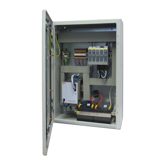
Page 8: P Roduct Description
Fig.: 1 Product t description of th he MZ3 modular control panel (ex xample of a sma ll modular contro ol panel) Mains s supply with i nternal discon... -
Page 9: T Echnical Specifications
Pos: 23 /Technische Dokumentation/Überschriften/Technische Daten @ 0\mod_1375869225879_567.docx @ 575 @ 1 @ 1 Tech hnical sp pecificati ions Pos: 24 /STG-BEIKIRCH Technische Dokumentation/Technische Daten STG/Technische Daten MZ3 @ 1\mod_145 55712857534_567.docx @ 14174 @ 2222222 @ 1 witch cabin net dimens sions Output cur... -
Page 10: A Ccumulators
cumulator The emergen ncy power sup pply via accum mulators is ens sured through proper design n and regular maintenance. If the mains supply voltag ge fails, the MZ Z3 modular co ontrol panel ca an open the co onnected SHE E drives at lea ast 2x and clos se 1x after 72... -
Page 11: Requirements On The Installation Site
Pos: 26 /Technische Dokumentation/Überschriften/Anforderung an den Aufstellort @ 1\mod_1455717202830_567.docx @ 14234 @ 2 @ 1 Requirements on the installation site Pos: 27 /STG-BEIKIRCH Technische Dokumentation/Technische Daten STG/Anforderungen an den Aufstellungsort MZ3 @ 1\mod_1455716918750_567.docx @ 14227 @ @ 1 Installation and ambient conditions according to DIN 12101-9... -
Page 12: P Ackaging, Transport And Storage
7_567.docx @ 13688 @ 1 @ 1 Pack kaging, t transport t and sto orage Pos: 32 /STG-BEIKIRCH Technische Dokumentation/Verpackung STG/Verpackung Modulzentrale MZ3 @ 1\mod_1 1455714360053_567.docx @ 14182 @ @ 1 The modular control panel is packed in a a cardboard b... -
Page 13: Installation
Pos: 41 /STG-BEIKIRCH Technische Dokumentation/Installation STG/MZ3/Schaltschrank montieren MZ3 @ 1\mod d_1455717281260_567.docx @ 14241 @ 2 @ 1 stalling the e switch c abinet The modular... -
Page 14: E Lectrical Connection
Pos: 43 /STG-BEIKIRCH Technische Dokumentation/Installation STG/MZ3/Elektrischer Anschluss MZ3 @ 1\mod_1 1455718891660_567.docx @ 14255 @ 22 @ 1 ectrical co nnection The mains fe eed of modula r control pane el MZ3 must be e fused separ ately on site a... -
Page 15: S Ample Cabling Diagram
Pos: 45 /STG-BEIKIRCH Technische Dokumentation/Installation STG/MZ3/Musterverkabelungsplan @ 1\mod_1455 55719423090_567.docx @ 14262 @ 2 @ 1 mple cabl ing diagra Fig.: 4 Example e cabling diagram m for the MZ3 mo odular control pa anel The valid pro ovisions regard ding cabling w with 30 min. -
Page 16: C Able Cross-Section Calculation
ble cross- -section c alculation Formula fo or cable cross s-section calc culation * The feed a and return con nnecting wires s are taken into to account in t he calculation formula, the erefore only ca alculate a sing gle line length. Fig.: 5 Formula a for cable cross- -section calculat... -
Page 17: C Able Cross-Section Table
Pos: 47 /STG-BEIKIRCH Technische Dokumentation/Installation STG/MZ3/Anschluss von Aktoren am Motoren Mod odul (MM) @ 1\mod_1455778658004_567.docx @ 14314 @ 2 @ 1 nnection o of actuato ors to the m... -
Page 18: C Onnection To The Ventilation Module (Lm)
Pos: 49 /STG-BEIKIRCH Technische Dokumentation/Installation STG/MZ3/Anschluss am Lüftungs-Modul (LM) @ 1 1\mod_1455778769996_567.docx @ 14321 @ 2 @ 1 nnection t to the ven ntilation m module (LM The sensors* * can be conn ected at any l evel. 3 different se... - Page 19 With a TS 1 1030 tempera ature sensor Fig.: 10 Switch ing diagram for c connecting sens sors to the ventila ation module Vent s switch LTA 11 Temperatur e sensor T 10 Selec ctor switch WH HA 14 Ventilation m module (LM) With two T TS 1030 tempe...
- Page 20 DIN EN 623 305/VDE 0185 5-305:2006. Wind direc ction encoder r and MZ3 sig gnal converte Fig.: 13 Switch ing diagram for c connecting sens sors to the ventila ation module RJ 12...
-
Page 21: C Onnection To The She Module (Rm)
Pos: 51 /STG-BEIKIRCH Technische Dokumentation/Installation STG/MZ3/Anschluss am RWA-Modul (RM) @ 1\m mod_1455779054976_567.docx @ 14328 @ 2 @ 1 6.10 Con nnection t to the SHE E module (RM) An SHE ma anual call po int type RBH/ Seve eral SHE man... - Page 22 Connection n of the fire d detection sys stem (BMA) UEB2-AE/2* m module is insta alled in the fire e detection syste Fig.: 16 Switch ing diagram for c connecting sens sors to the SHE m module UEB2 2-AE/2* BMA switch contact on sit Pos: 52 /Technische Dokumentation/Seitenumbruch @ 0\mod_1375798861029_567.docx @ 572 @ @ 1 Article-...
-
Page 23: C Onnection To The Iom Module (Iom)
IOM m module Pos: 54 /STG-BEIKIRCH Technische Dokumentation/Installation STG/MZ3/Anschluss am Installation Bus (Eib) – K Konnex (KNX) – Modul @ 1\mod_1455779221194_567.docx @ 14342 @ 2 @ 1 6.12 Con nnection t... -
Page 24: C Ommissioning
Pos: 57 /Technische Dokumentation/Überschriften/Vorbereitende Maßnahmen @ 0\mod_1377697298577_567.doc cx @ 644 @ 2 @ 1 eparatory measures Pos: 58 /STG-BEIKIRCH Technische Dokumentation/Vorbereitende Maßnahmen STG/Vorbereitende Maßnahmen MZ3 @ 1\mod_1460536341199_567.docx @ 14666 @ 2 @ 1 Before comm missioning the MZ3 modular r control panel... - Page 25 Master modu (AM, MM M, LM Modu le not configur (RM or LM) and EAM Fig.: 22 MZ3 m odular control pa anel ready for op peration ► The mod dules are in op perating mode e, no error is p present.
-
Page 26: F Unctional Test And Test Run
Pos: 60 /STG-BEIKIRCH Technische Dokumentation/Inbetriebnahme STG/MZ3/Funktionstest und Probelauf @ 1\m mod_1460547229420_567.docx @ 14673 @ 2333333 @ 1 nctional te est and te st run Note Depending o on the configu uration, openin ng widths, time es and reactio ons can vary. -
Page 27: F Unctional Test Of The She* Manual Call Point
7.3.3 Functional t test of the SHE* man ual call po Function Actual s status ration Result SHE* trigge ering. The SHE E* manual cal The linked actuators* ► Actuate the re ed "SHE* point is ready for oper ration, (such moto or outputs) OPEN"... -
Page 28: F Unctional Test Of The Automatic Detector
7.3.4 Functional t test of the automatic detector Function Actual s status ration Result SHE* trigge ering by SHE* is ready for The linked actuators* ► Set the assig automatic d detector. operatio (such moto or outputs) automatic det tector in move to 10 00 % in the revision mode... -
Page 29: F Unctional Test Of Rain Detector/ Wind/Rain Detector
Reset of the e automatic The linke d actuators* The red LED indicator in ► lear the autom matic detector. (such as motor outputs the automatic c detector etector of smo are in the e "CLOSE goes out. position" to 0 %. A reset t of the autom atic... -
Page 30: F Unctional Test Of The Emergency Power
Error message on the AM ► wer down the MZ3. power oper ration. module display Mains volta age on MZ3 The assigned a actuators* ► tuate the assig gned modular co ntrol panel re not given a an "OPEN nt switch in the e "OPEN... -
Page 31: M Z3 Modular Control Panel Reset
MZ Z3 modular co ntrol panel. Pos: 61 /STG-BEIKIRCH Technische Dokumentation/Inbetriebnahme STG/MZ3/Modulzentrale MZ3 RESET @ 1\m mod_1460979726947_567.docx @ 14721 @ 3 @ 1 7.3.7 MZ3 modula ar control p panel reset See subchap pter "Menu gui... -
Page 32: O Peration
Pos: 63 /Technische Dokumentation/Überschriften/Bedienung @ 1\mod_1433145251749_567.docx @ 12571 @ 1 @ Oper ration Pos: 64 /STG-BEIKIRCH Technische Dokumentation/Bedienung STG/MZ3/Funktionsbeschreibung Module @ 1\mo od_1455781864686_567.docx @ 14358 @ 2 @ 1 nctional d description n of the m modules Fig.: 24 Descrip... -
Page 33: A Ccumulator Module (Am)
Pos: 66 /STG-BEIKIRCH Technische Dokumentation/Bedienung STG/MZ3/Akkumulatoren-Modul (AM) @ 1\mod_1 1455782062493_567.docx @ 14374 @ 3 @ 1 8.1.1 Accumulato or module (AM) The accumul lators module (AM) is intend ded for the foll lowing functio ons: • Charging g and monitor... -
Page 34: M Otor Module (Mm)
Pos: 68 /STG-BEIKIRCH Technische Dokumentation/Bedienung STG/MZ3/Motoren-Modul (MM) @ 1\mod_145578 82300216_567.docx @ 14381 @ 2 @ 1 otor modul le (MM) The motor m odule (MM) is s intended for t the following f functions: • Control o of actuators*, e.g. motors, m magnetic clam mps. -
Page 35: V Entilation Module (Lm)
Pos: 70 /STG-BEIKIRCH Technische Dokumentation/Bedienung STG/MZ3/Lüftungs-Modul (LM) @ 1\mod_1455784 84098888_567.docx @ 14388 @ 2 @ 1 ntilation m module (LM The ventilatio on module (LM M) is intended for the followi ing function: • Control o of sensors* th at are connec... - Page 36 Connection n data Cable cross s-section rigid and flexible 0.14 – 1.5 m Cable cross s-section flexib ble with wire 0.25 – 0.5 m end sleeve with plastic sl eeve Cable cross s-section flexib ble with wire 0.25 – 1.5 m end sleeve without plastic c sleeve...
-
Page 37: She Module (Rm)
Pos: 72 /STG-BEIKIRCH Technische Dokumentation/Bedienung STG/MZ3/RWA-Modul (RM) @ 1\mod_145578420 01459_567.docx @ 14395 @ 2 @ 1 E module (RM) The SHE mo odule (RM) is i ntended for th he following fu unction: • Connect tion of SHE* m manual call po ints. -
Page 38: B Oard With Button Battery
Pos: 74 /STG-BEIKIRCH Technische Dokumentation/Bedienung STG/MZ3/Platine mit Knopfbatterie @ 1\mod_1469 69535821977_567.docx @ 15504 @ 2 @ 1 ard with b button batt tery The board wi ith button batt ery is intende d for the follow wing function: • Storing t the system tim Fig.: 29 Descrip... -
Page 39: I Nput/Output Module (Iom)
Pos: 76 /STG-BEIKIRCH Technische Dokumentation/Bedienung STG/MZ3/Eingabe / Ausgabe-Modul (EAM) @ 1\m mod_1455784268617_567.docx @ 14402 @ 2 @ 1 put/output module (I IOM) The input/out tput module (I OM) is intend ed for the follo owing function • Exchang ging digital sta... -
Page 40: C Ombination Of Smart Connect Knx* And Ifm1 Modules
Pos: 78 /STG-BEIKIRCH Technische Dokumentation/Bedienung STG/MZ3/Kombination smart connect-Modul und I IFM1-Modul @ 1\mod_1455784401920_567.docx @ 14416 @ 2 @ 1 mbination n of smart connect K KNX* and IFM1 mod dules The combina ation of the sm mart connect m module and the... -
Page 41: S Mart Connect Module
Pos: 80 /STG-BEIKIRCH Technische Dokumentation/Bedienung STG/MZ3/Smart connect Modul @ 1\mod_145578 84458533_567.docx @ 14423 @ 2 @ 1 mart conne ect module The smart co onnect module e is intended fo or the followin ng function: • Interface e for the STG- -BEIKIRCH KN NX network. -
Page 42: I Fm1 Module
Pos: 82 /STG-BEIKIRCH Technische Dokumentation/Bedienung STG/MZ3/IFM1-Modul @ 1\mod_1455784524974_ 4_567.docx @ 14430 @ 2 @ 1 M1 module The IFM1 mo odule is intend ded for the foll owing function • The IFM M1 module is a an interface mo odule for comm... -
Page 43: C Onfiguration Options Of The Modules
Pos: 84 /STG-BEIKIRCH Technische Dokumentation/Bedienung STG/MZ3/Konfiguration der Module @ 1\mod_146 60379821554_567.docx @ 14652 @ 233 @ 1 8.10 Con nfiguratio on options s of the mo odules The MZ3 mo dular control p panel is config gured in the fa... -
Page 44: Special Items
Sensors* e.g. temperature, CO , humidity… can be integrated directly via a 4-20 mA interface. • Motor modules with 3 outputs with max. 8 amps each that can be coupled via the MZ3 software. • Selection of various ventilation priorities. -
Page 45: M Enu Guidance
Pos: 86 /STG-BEIKIRCH Technische Dokumentation/Bedienung STG/MZ3/Menüführung MZ3 @ 1\mod_14609811 53865_567.docx @ 14728 @ 2 @ 1 8.11 Me nu guidan menu guidanc ce of the mod dules is alwa ays controlled via the button ns (2). Short button press: To me ... -
Page 46: M Z3 Tool Software
Pos: 88 /STG-BEIKIRCH Technische Dokumentation/Bedienung STG/Software MZ3/Software MZ3 @ 1\mod_1455 5786657105_567.docx @ 14438 @ 233333333233333 @ 1 8.12 MZ Z3 tool sof ftware The "MZ3 too ol" software is s required for t he planning a and configurati ion of the MZ3 3 modular con ntrol panel. -
Page 47: I Nstalling The Software
► Confirm with "OK". Note Please read d the license a agreement bef fore installing the MZ3 tool software. If yo ou accept all o of the conditions o of the agreem ent, select the e correspondin ng option and press the "Co... -
Page 48: I Nstalling The Converter
Caution User group for the "MZ3 T Tool" software e must be sele ected before " "Confirm insta allation". ► Select the def fault target dir rectory "C:\Pro ogram Files(x86)\MZ Z Tool" again. If you want to o install the pro... - Page 49 ► Confirm w with "OK". The driver r is installed. The installatio on window of t the "MZ3 tool" " opens. ► Confirm with "Complete". The "MZ3 too l" software is i installed. ► Connect the c converter to th he computer.
-
Page 50: D E-Installing The Software
7 and high Contro ol panel/All co ntrol panel ele ements: "Selec ct programs a and functions". Select t the "MZ3 too l" program. Select t "De-install". Confirm m de-installati ion with "Yes" Article- -no.: 1342499... -
Page 51: O Bject Data/Configuration Data Of The Mz3 Tool
8.13 Obj ject data/c configurat tion data o of the MZ3 3 tool 8.13.1 nstalling ne ew configu uration data elete addresse ► ► Then keep p the button pressed u until both ► n the master points app pear. -
Page 52: R E-Assigning The Address Assignment Of The Modules
► n the master odule, press t The MZ3 tool deletes p button 3x un ntil the old ad ddressing. "A Ar" appears on n the splay. ►... - Page 53 Power down t the modular c control panel. ► Disconnect th he accumulato ors first. ► Then disconn nect the mains s supply cable ► Push the old Micro SD mem mory card to u unlock and remove it. ►...
-
Page 54: R Eplacing The Configuration Data Via Usb Converter
"Ar" appears on the display ► Then keep th e button press sed until both points appear. The MZ3 tool deletes the o old addressing The master m module display ys "_". All other mod ules display "- - -". - Page 55 ► Connect the U USB plug to th he PC. Read ding the new configuratio ► Start the MZ3 3 tool in config guration mode ► Click the "Cle ear" button. ► Confirm with "Yes" An 8 and a ci rculating bar a appears.
-
Page 56: A Ssigning The Address Assignment Of The Modules
► n the master odule, press t the top utton 2x until " "Ad" ppears on the splay. ► The MZ3 3 tool asks for r the individua lly assigned a addresses. ► Assign t the module ad ddresses noted... -
Page 57: M Aintenance And Repairs
@ 1974 @ 1 @ 1 Main ntenance e and rep pairs Pos: 91 /STG-BEIKIRCH Technische Dokumentation/Sicherheit STG-BEIKIRCH/Wartungs- und Instandhaltungspfli icht MZ3 @ 1\mod_1455711456967_567.docx @ 14149 @ 2 @ 1 NSHE’s* and d SHE* system ms are safety i nstallations fo or precautiona ary fire protect ion. -
Page 58: T Ransmission Of Messages
Pos: 93 /STG-BEIKIRCH Technische Dokumentation/Wartung STG/Wartung / Instandsetzung MZ3 @ 1\mod_1455 5792775051_567.docx @ 14484 @ 2222 @ 1 If the product t is used in sa afety systems, such as smok ke and heat ex xtraction syste ems (SHE*), it... -
Page 59: M Alfunction Messages
lfunction messages Malfunctions in the control system/modu ular control pa anel are shown n on the displa ays of the mod dules. Depend ding on the malfunction, the malfunctio on codes can be expanded by pressing th he button. This s enables a de etailed display y of the... - Page 60 Modul Main error Sub-error r message Flash h code/malfu nction descri iption message oint Type 1x flashing g, yellow LED 230 / 400 Volt AC p power supply has failed 2x flashing g, yellow LED Accu mulators defe ctive 3x flashing g, yellow LED Malfu unction on ass...
- Page 61 Modul Main error Sub-error r message anual Flash h code/malfu nction descri iption message Type oint 4x fla ashing Autom matic detector r malfunction 4x fla ashing Short t-circuit on the e detector line 4x fla ashing Line d disconnection on the detect tor line 4x fla...
- Page 62 Modul Main error Sub-error r message anual Flash h code/malfu nction descri iption message Type oint 9x fla ashing Outsi ide temperatu 9x fla ashing Wind direction enc oder 9x fla ashing LM/MM Sens or value miss 10x f flashing RM/LM Syste em time not se...
-
Page 63: T Roubleshooting
oubleshoo oting Caution Danger to li fe from electri ic shock. Work on the e mains supply y must only be e carried out b by an electricia Mains conn nection malfu unction ause Measu The green " "Operation 0 / 400 Volt A Mains connection no ot in order. - Page 64 Automatic detector mal lfunction Meas sure The green tomatic detect Supp ply cable not in n order. "Operation OK" LED lfunction Check the su upply cable for r damage. on the SHE E* manual Check that th he connection terminals call point do oes not...
- Page 65 GLT h caus se or error. LED on the SHE* gistered an er rror on manual call l point e MZ3 modula does not lig ght. The ontrol panel. yellow "Malfunction n" LED flashes 7-tim All modules s display error messa age.
-
Page 66: T Aking Out Of Operation
"E12 3" " necessary. Pos: 94 /STG-BEIKIRCH Technische Dokumentation/Wartung STG/Außerbetriebnahme Produktneutral @ 1\mod_1 1460970526257_567.docx @ 14714 @ 2 @ 1 king out o of operatio In order to ta ke the system... -
Page 67: D Ismantling/Disposing
Certified ele ectricians mus st disconnect t the supply in t he switch cab binet. Pos: 98 /STG-BEIKIRCH Technische Dokumentation/Entsorgung STG/Entsorgung STG Allgememein @ 1\mod_14 455787715383_567.docx @ 14446 @ 2 @ 1 10.1 Dis sposal The electrica al device must... -
Page 68: 11 Glossary
Pos: 100 /Technische Dokumentation/Überschriften/Glossar @ 0\mod_1377173247503_567.docx @ 597 @ 1 @ 1 11 Glossary Pos: 101 /STG-BEIKIRCH Technische Dokumentation/Glossar/Glossar MZ3 @ 1\mod_1465203091090_567.docx @ 15095 @ @ 1 A smoke and heat extraction system (SHE) is used for precautionary fire protection and, in the event of a fire, should extract the fire smoke from buildings to the outside as quickly as possible. - Page 69 The LON system is a bus system, based on the LonWorks® bus technology (where LON as an SHE bus system LON stands for Local Operating Network). A structure of remotely controlled networks is made possible with the aid of this bus engineering. The basic component is Neutron Chip from Echelon.
- Page 70 Pos: 103 /Technische Dokumentation/Impressum / Copyright/STG BEIKIRCH @ 1\mod_1460985861312_567.docx @ 14735 @ @ 1 STG-BEIKIRCH Industrieelektronik + Sicherheitstechnik GmbH & Co. KG Trifte 89 32657 Lemgo, Germany T + 49 5261 9658-0 F + 49 5261 9658-66 info@stg-beikirch.de www.stg-beikirch.de === Ende der Liste für Textmarke Inhalt === Article-no.: 13424999549...
Need help?
Do you have a question about the MZ3 and is the answer not in the manual?
Questions and answers