
Related Manuals for Bertazzoni CB486G00X


Summary of Contents for Bertazzoni CB486G00X
- Page 1 (GB) INSTRUCTIONS FOR THE INSTALLATION, MAINTENANCE pag. 7 AND USE OF FIXED HOBS 48’’( ) (W) x 25 ) (D) 1216 mm 1/8’’ 640mm...
-
Page 2: Table Of Contents
READ THE INSTRUCTION BOOKLET BEFORE INSTALLING AND USING THE APPLIANCE. These instructions are valid only for those countries which are indicated by their identification symbol on the front cover of the instruction booklet and on the label on the appliance. The manufacturer cannot be held responsible for any damage to things or persons caused by an incorrect installation or by incorrect use of the appliance. - Page 3 The hob can be installed by itself, in an isolated position or inserted between two kitchen units or between one kitchen unit and a wall. Furthermore the back wall and surrounding surfaces must resist a temperature of 65 K. To prevent the plastic layer which covers the kitchen unit from ungluing, the glue used to join the two surfaces together must resist temperatures of up to 150 °C The installation of the appliance must be carried out according to the norms in force of the country concerned and the appliance must be installed in a well ventilated place.
-
Page 4: Connection To The Electricity Supply
To regulate the minimum on the burners carry out the following procedure indicated below: 1) Turn on the burner and put the knob onto position MINIMUM ( small flame ). 2) Remove the knob ( Fig. 11) of the tap which is set for standard pressure. The knob is found on the bar of the tap itself. 3) Beside the tap bar on the w ork top, use a small screw driver that fits the screw (gold) found on the low er part of the tap (F ig. -
Page 5: Use Of The Burners
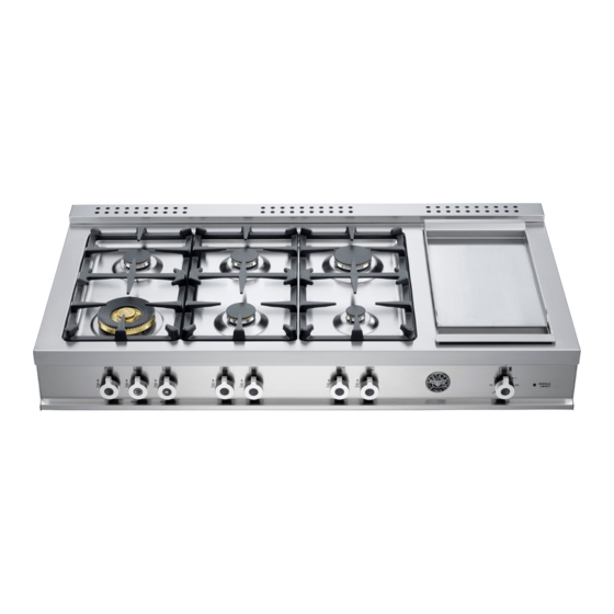
Table 4 GAS BURNER DIMENSION (fig.13-14) DESCRIPTIVE CAPTION FOR HOB (fig.13) 1. Small Burner 2. Medium burner 3. Rapid burner 4. Dual burner 5. Griddle CONTROL PANEL DESCRIPTION On the control panel, small sy mbols show the function of each knob or key. Here as follows are the several controls that a cooker can have: the symbol shows the disposition of burners on the worktop, the full dot identifies the burner in object (in... -
Page 6: Cleaning Of The Appliance
The griddle element is hot after use. Allow sufficient time for griddle components cool before cleaning. The electric griddle element is rated 120 volts AC 1100 watts. Seasoning the griddle Before using the griddle for the first time, it must be seasoned. If the griddle has not been used for a period of time, it should be reseasoned. - Page 7 ATTENTION: for further details about cleaning of the appliance, please contact your applliance retailer. Fig.1 Fig.2 Fig.3 Fig.4...
- Page 8 Fig.5 Fig.6 Fig.7 Fig.8 Fig.9 Fig.10...
- Page 9 Fig.11 Fig.12 Fig.13 Fig.14 Fig.15 Fig.16...
- Page 11 ...
- Page 12 310779...
Need help?
Do you have a question about the CB486G00X and is the answer not in the manual?
Questions and answers