Table of Contents
Advertisement
Quick Links
Advertisement
Table of Contents

Related Manuals for Pepperl+Fuchs OIT500-F113-B17-CB


Summary of Contents for Pepperl+Fuchs OIT500-F113-B17-CB
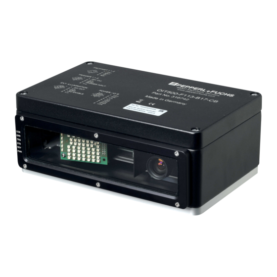
- Page 1 OIT500-F113-B17-CB High-Temperature Identification System Manual...
- Page 2 Phone: +49 621 776 - 0 E-mail: info@de.pepperl-fuchs.com North American Headquarters Pepperl+Fuchs Inc. 1600 Enterprise Parkway Twinsburg, Ohio 44087 Phone: +1 330 425-3555 E-mail: sales@us.pepperl-fuchs.com Asia Headquarters Pepperl+Fuchs Pte. Ltd. P+F Building 18 Ayer Rajah Crescent Singapore 139942 Phone: +65 6779-9091 E-mail: sales@sg.pepperl-fuchs.com https://www.pepperl-fuchs.com...
-
Page 3: Table Of Contents
OIT500-F113-B17-CB Contents Introduction........................ 5 Content of this Document ................5 Target Group, Personnel ................5 Symbols Used ....................6 Registered Trademarks ................. 6 Product Description ....................7 Functional Description .................. 7 Application and Areas of Use ............... 7 LED Indicator ....................8 Interfaces and Connections ............... - Page 4 OIT500-F113-B17-CB Contents Parameterization Using Vision Configurator............45 Screen Layout ....................46 Menu Bar.......................47 5.2.1 File Menu ..................47 5.2.2 View Menu ..................47 5.2.3 Sensor Menu..................48 5.2.4 Image Menu ..................49 5.2.5 Administration Menu ................ 49 5.2.6 Help Menu..................49 Toolbar ......................50 Result View ....................51 Extended State .....................53...
-
Page 5: Introduction
OIT500-F113-B17-CB Introduction Introduction Content of this Document This document contains information required to use the product in the relevant phases of the product life cycle. This may include information on the following: • Product identification • Delivery, transport, and storage •... -
Page 6: Symbols Used
OIT500-F113-B17-CB Introduction Symbols Used This document contains symbols for the identification of warning messages and of informative messages. Warning Messages You will find warning messages, whenever dangers may arise from your actions. It is mandatory that you observe these warning messages for your personal safety and in order to avoid prop- erty damage. -
Page 7: Product Description
Product Description Functional Description OIT500-F113-B17-CB (referred to as the OIT system from now on) uses infrared lighting and evaluates special code sheets that feature hole patterns. For this purpose, the OIT system is fit- ted with a normal lens and an internal LED board for illuminating the code sheets. The infrared lighting guarantees optimal contrasts during a read operation, so that even soiled code sheets can be reliably identified. -
Page 8: Led Indicator
OIT500-F113-B17-CB Product Description LED Indicator The LED indicator shows all important system and status information. The nine LEDs mounted on the side of the device can be used to read different information. Figure 2.2 LED Indicator Position Description Function GOOD Reading successful (green) or failed (red) The LED flashes while initializing. - Page 9 OIT500-F113-B17-CB Product Description Figure 2.3 Lighting unit of the OIT system Position Description Function Code OK Reading successful Error Lights up red when a read error occurs Trigger Lights up yellow when a connected trigger sensor is activated Stability of...
-
Page 10: Interfaces And Connections
OIT500-F113-B17-CB Product Description Interfaces and Connections Figure 2.4 Connections 1. PROFINET/EtherNet TCP/IP connection 1 2. PROFINET/EtherNet TCP/IP connection 2 3. Trigger connection 1 4. Trigger connection 2 5. Power supply 6. Connection for external lighting Pinout for PROFINET Connection 1 and 2 Figure 2.5... - Page 11 OIT500-F113-B17-CB Product Description Pinout for Trigger Connection 1 and 2 Figure 2.6 Pinout for Trigger Connection 1. 24 V power supply 2. Not assigned 3. Ground 4. Trigger signal 5. Not assigned Pinout for Power Supply Figure 2.7 Pinout for power supply 1.
-
Page 12: Scope Of Delivery
OIT500-F113-B17-CB Product Description Pinout for External Lighting Figure 2.8 Pinout for external lighting 1. 24 V power supply 2. Not assigned 3. Ground 4. Lighting control 5. Not assigned Scope of Delivery Check the packaging and contents for damage. Check if you have received every item and if the items received are the ones you ordered. -
Page 13: Accessories
OIT500-F113-B17-CB Product Description Accessories Various accessories are available. 2.6.1 Power Supply Description Description V19-G-2M-PUR-ABG Single-ended female cordset, M12, 8-pin, shielded, PUR cable V19-G-ABG-PG9 M12 single-ended female cordset, 8-pin, shielded, field-attach- able 2.6.2 Connection Cable for Trigger Sensors and External Lighting Use the following connection cable to connect a trigger sensor or external lighting. -
Page 14: Network Cable
OIT500-F113-B17-CB Product Description 2.6.3 Network Cable Note Network Connection with Degree of Protection IP65 The network connection on the OIT has degree of protection IP65. The OIT is connected to the network via a network connector. Description Description V1SD-G-2M-PUR-ABG-V45-G 2 m cordset, M12 to RJ45 PUR cable, 4-pin, CAT5e... -
Page 15: Code Sheets
OIT system. Figure 2.9 CB1 code sheet Figure 2.10 CB3 code sheet Note Ordering Code Sheets The CB1 code sheet can be ordered from Pepperl+Fuchs. The CB3 code sheets are still on the market, but cannot be ordered from Pepperl+Fuchs. - Page 16 OIT500-F113-B17-CB Product Description Note Contamination of the Code Sheet Protect the code sheet from excess dirt. The code sheet can be cleaned using aggressive or abrasive cleaning agents. Ensure that no other markings are made on the code sheet, as this can affect the reading.
-
Page 17: Mounting And Installation
OIT500-F113-B17-CB Mounting and Installation Mounting and Installation OIT System Overview Figure 3.1 OIT system, structural principle The installation of the OIT system involves just a few steps. In addition to the EtherNet TCP/IP interface, the device has a trigger input for an optional trigger sensor (NBB20-L2-A2-V1 induc- tive sensor shown for illustrative purposes). -
Page 18: Mounting The Oit System
OIT500-F113-B17-CB Mounting and Installation Mounting the OIT System Warning! Danger to life due to defective mounting Errors during mounting can cause life-threatening injuries and significant property damage. • Ensure the installation is performed only by sufficiently trained and qualified personnel. - Page 19 OIT500-F113-B17-CB Mounting and Installation Permissible Code Sheet Displacement for CB1 Code Sheets ΔY ΔX Working distance in Z-direction Code sheet displacement in X- and Y-direction Figure 3.4 X/Y direction for the displacement of OIC-xxxx-CB1 Code sheet. Read range Δ X ΔY...
- Page 20 OIT500-F113-B17-CB Mounting and Installation Permissible Reading Window Displacement for CB1 Code Sheets ΔY ΔX Reading window in the X and Y direction Code sheet displacement in the X and Y direction Figure 3.6 X/Y direction for the displacement of OIC-xxxx-CB1 code sheets...
-
Page 21: Setting The Lighting Angle
OIT500-F113-B17-CB Mounting and Installation 3.2.2 Setting the Lighting Angle For optimal detection of the perforated matrix, code sheets must be illuminated at a certain angle to achieve maximum contrast between the holes and the metal plate. The angle must be set manually depending on whether you use CB1 or CB3 code sheets. - Page 22 OIT500-F113-B17-CB Mounting and Installation Figure 3.8 Positioning on the rail (CB3) Move the lighting unit along the rail to the CB3 position. Tighten the two hexagon socket cap head screws to a torque of 1.5 Nm. Screw the enclosure cover back down.
-
Page 23: Mounting The Device
OIT500-F113-B17-CB Mounting and Installation 3.2.3 Mounting the Device The device has a preassembled mounting base with four symmetrically positioned M6 threads on the base of the housing for easier installation. The illustration below shows all the relevant housing dimensions in mm: 4 x M6 Figure 3.10... -
Page 24: Mounting The Code Sheet
OIT500-F113-B17-CB Mounting and Installation 3.2.4 Mounting the Code Sheet Aligning/Adjusting Code Sheets The OIT system is set to a reading distance of 380 mm by default. Mount the code sheets parallel with the front panel, so that the lens faces the code sheet. The tilt angle must not exceed 10°. -
Page 25: Establishing An Electrical Connection
OIT500-F113-B17-CB Mounting and Installation Establishing an Electrical Connection Figure 3.13 Connections 1. PROFINET/EtherNet TCP/IP connection 1 2. PROFINET/EtherNet TCP/IP connection 2 3. Trigger connection 1 4. Trigger connection 2 5. Power supply 6. Connection for external lighting Providing a Power Supply To supply voltage to the OIT system, proceed as follows: Insert the 8-pin M12 connector into the plug provided on the side of the housing. - Page 26 OIT500-F113-B17-CB Mounting and Installation Creating a PROFINET/EtherNet TCP/IP connection For the initial commissioning of the device, connect the device directly to the PC/laptop: Plug the 4-pin M12 plug (D-coded) into the socket provided for this purpose on the side of the housing.
-
Page 27: Setting Up Windows Network Communication Between The Device And A Pc/Laptop
OIT500-F113-B17-CB Mounting and Installation Setting up Windows Network Communication between the Device and a PC/Laptop The OIT system is delivered with a fixed IP address (192.168.2.5). To enable communication within the network, the network settings of your PC/laptop must be synchronized with the device and may need to be adjusted. - Page 28 OIT500-F113-B17-CB Mounting and Installation • The "MAC address" of the device • And the "Firmware" Setting the IP Address of the PC The following section describes how to check the network connection settings of your Windows PC and adapt them accordingly. The illustrations in this description were created using Windows 7.
- Page 29 OIT500-F113-B17-CB Mounting and Installation The Properties window for the TCP/IP protocol opens. Select the "General" tab. Select the input function "Use the following IP address." Use the device's IP address that you found using the "Auto-detect function." In this example, enter the following IP address and subnet mask: •...
- Page 30 OIT500-F113-B17-CB Mounting and Installation Click OK, and click Cancel in the next dialog. This completes the network configuration so that the device can be used. Note Changes to the network settings of the PC/laptop require advanced user rights. If necessary, consult with your administrator.
-
Page 31: Connecting The Oit System With Vision Configurator
OIT500-F113-B17-CB Mounting and Installation Connecting the OIT System with Vision Configurator Establishing a Connection Start the Vision Configurator software. Enter your user name and password, see chapter 5. Double-click on the device type OIT (1). Figure 3.15 Selecting the device Click on Ok (2) to confirm your selection. -
Page 32: Commissioning
OIT500-F113-B17-CB Commissioning Commissioning Integrating the OIT System into the Network Warning! Risk of injury due to incorrect configuration An error during the configuration of the device can override the fail-safe function, causing a danger to people and machinery. • Ensure that the device is programmed exclusively by qualified personnel. - Page 33 OIT500-F113-B17-CB Commissioning Figure 4.2 Search for GSDML file Click the "button with the three dots" (1), which allows you to search for your GSDML file on the storage medium. Select your GSDML file (2) and click "OK" (3) to confirm your selection.
- Page 34 OIT500-F113-B17-CB Commissioning Integrating a Device into the Project Open the hardware catalog and browse through the tree structure until you see your device (1). Note The figures are provided to aid basic understanding and may deviate from the actual design.
- Page 35 OIT500-F113-B17-CB Commissioning To connect the device with the control panel, move the mouse to the PROFINET interface that is highlighted in green in the control panel (1). Click the left mouse button and drag the line shown to the PROFINET interface on the device (2). Once there, release the left mouse button again.
- Page 36 OIT500-F113-B17-CB Commissioning Compiling a Project Configuration The project configuration must be compiled before it is transferred to the control panel. During compilation, the project configuration is converted such that it can be read by the control panel. Figure 4.7 Compiling a project configuration In the project tree, right-click on the control panel and select "PLC_1*"...
- Page 37 OIT500-F113-B17-CB Commissioning Loading the Project Configuration into the Control Panel To load the project configuration into the control panel, proceed as follows: Figure 4.8 Loading project configuration In the project tree, right-click on the control panel and select "PLC_1*" (1) and select "Load into device"...
- Page 38 OIT500-F113-B17-CB Commissioning Creating Tag Tables A tag table must be created to be able to watch or control measured values. In the tag table, you can assign tags to input addresses or output addresses and allocate tag names. The names are valid throughout the control panel.
- Page 39 OIT500-F113-B17-CB Commissioning Note Address Range Figure 4.11 Address range The address designations in this example are project-dependent and may differ from your actual address assignment. The memory range is automatically assigned by the TIA Portal when the modules are integrated into the project.
- Page 40 OIT500-F113-B17-CB Commissioning In the project tree, click on Watch and force tables and double-click on Add new watch table (4). Click the field in the Address column (2). A list of addresses that you have defined in the tag table is displayed.
-
Page 41: Parameterization
OIT500-F113-B17-CB Commissioning Parameterization The factory default parameters are entered in the OIT memory. You can adjust the parameters using the "TIA Portal" configuration software. The OIT system can also be parameterized via the "Vision Configurator," see chapter 5. Opening the Parameter Table Figure 4.13... - Page 42 OIT500-F113-B17-CB Commissioning Figure 4.14 Configuration module_1 The "module parameters" can be accessed from the "General" tab. You can parameterize your data here. The table below shows you which parameters you can adjust.
- Page 43 OIT500-F113-B17-CB Commissioning Global Primary Data The global primary data allows you to parameterize the OIT system using PROFINET. Global primary data is always transferred to the OIT system in full. Configuration Parameters Module parameters Parameter ID Data type Value Description...
- Page 44 OIT500-F113-B17-CB Commissioning Module parameters Parameter ID Data type Value Description CB3 settings CB3 orientation 8 bit 0 ... 3 (default: 0) Determines the alignment 0 = 0: normal of the code sheet in the 1 = 0: mirrored sensor image 2 = 180: rotated by 180°...
-
Page 45: Parameterization Using Vision Configurator
OIT500-F113-B17-CB Parameterization Using Vision Configurator Parameterization Using Vision Configurator The OIT system can be parameterized using the Vision Configurator software. Introduction to the Vision Configurator Operating Software The Vision Configurator software has a user-friendly interface that makes it easy to operate the sensor. -
Page 46: Screen Layout
OIT500-F113-B17-CB Parameterization Using Vision Configurator Screen Layout The application screen opens after you log in. Note The individual functions are dependent on the selected user role. Figure 5.1 Application screen 1. The Result View displays the read images and offers basic editing tools. If the Show re- sults option is enabled, additional information, such as the required decoding time, is dis- played. -
Page 47: Menu Bar
OIT500-F113-B17-CB Parameterization Using Vision Configurator Menu Bar The menu bar contains a list of menu items. The functionality depends on the type of sensor that is connected and the permissions of the user logged in. Figure 5.2 Menu Bar 5.2.1 File Menu Figure 5.3... -
Page 48: Sensor Menu
OIT500-F113-B17-CB Parameterization Using Vision Configurator 5.2.3 Sensor Menu Figure 5.5 Sensor menu Load settings Loads the saved settings from the sensor Save settings Saves the settings to the sensor Reset device Resets the sensor to its default settings Change network settings Change the network settings. The settings window allows you to... -
Page 49: Image Menu
OIT500-F113-B17-CB Parameterization Using Vision Configurator 5.2.4 Image Menu Figure 5.6 Image menu Open image folder Opens the folder in which images are currently saved Save image Saves the image currently displayed on the PC Copy image to clipboard Loads an image file to the clipboard... -
Page 50: Toolbar
OIT500-F113-B17-CB Parameterization Using Vision Configurator Toolbar The toolbar contains various functions. Disconnects the connection between Vision Configurator and OIT. Opens locally saved settings. Saves settings locally. Reads the current settings from the OIT. Saves the current settings to the OIT. -
Page 51: Result View
OIT500-F113-B17-CB Parameterization Using Vision Configurator Result View The Result View provides different options for displaying captured images. The Show image and Show results check boxes can be used to activate and deactivate the image display and result display. Figure 5.9... - Page 52 OIT500-F113-B17-CB Parameterization Using Vision Configurator Toolbar The toolbar is located on the left side under the Result View tab. There are some useful func- tions in the toolbar which are used to further process recorded images. The following functions are available to you.
-
Page 53: Extended State
OIT500-F113-B17-CB Parameterization Using Vision Configurator Extended State The Extended State tab contains two sections. Warning messages are displayed in the upper section of the window and the status is displayed in the lower section. To enable subsequent evaluation of the warning and status messages, image captures must be set to single image mode. - Page 54 OIT500-F113-B17-CB Parameterization Using Vision Configurator Warning Message Warning message Description Remedy Camera image too The camera image is too bright. Set the right exposure time, see chapter bright 5.6.4. Camera image too The camera image is too dark. Set the right exposure time, see chapter dark 5.6.4.
-
Page 55: Configuration Window
OIT500-F113-B17-CB Parameterization Using Vision Configurator Configuration Window Various parameters are specified in the configuration window. The individual parameters depend on the current authorization level and are, therefore, not always all visible. Some fea- tures are available in different variants only. Depending on the parameters set, some fields will be grayed out. -
Page 56: Oit Tab
OIT500-F113-B17-CB Parameterization Using Vision Configurator 5.6.2 OIT Tab Global Menu Figure 5.15 OIT tab Global menu item Window Location X start X coordinate of the decoder frame in which the OIT attempts to read a perforated matrix Y start Y coordinate of the decoder frame in which the OIT attempts to read a perforated... -
Page 57: Interface Tab
OIT500-F113-B17-CB Parameterization Using Vision Configurator Code plate Menu Figure 5.16 OIT tab Code plate menu item Settings Orientation Setting for the alignment of the CB3 code sheet • 0 degree normal: normal • 0 degree mirrored: mirrored • 180 degree normal: rotated by 180°... -
Page 58: Camera Tab
OIT500-F113-B17-CB Parameterization Using Vision Configurator 5.6.4 Camera Tab Image Menu Figure 5.18 Camera tab Transfer menu item Transfer Image transfer active Activates image transfer to Vision Configurator View on error Determines which image should be transferred to Vision Configu- rator after a failed reading. If the capture of two images for one read operation has been activated (see chapter 5.6.2), only one... - Page 59 OIT500-F113-B17-CB Parameterization Using Vision Configurator Acquisition Menu Figure 5.19 Camera tab Setting or Live image menu item Positions Exposure time Exposure time setting in µs Min. = 10 µs, max. = 10,000 s Default setting: 1500 µs Gain Gain setting Min.
-
Page 60: Control Tab
OIT500-F113-B17-CB Parameterization Using Vision Configurator 5.6.5 Control Tab Figure 5.20 Control tab, Setup menu item Trigger (inputs 1 and 2) Trigger input logic Logical And AND link: A trigger must be present so that the 2nd trigger sensor is activated. -
Page 61: Device Output
OIT500-F113-B17-CB Parameterization Using Vision Configurator Device Output This area displays an overview of the communication between Vision Configurator and the OIT system. Figure 5.22 Device output There are two buttons in the area at the bottom. Save output Saves the Sensor Output area in a text file. -
Page 62: Operation And Communication
OIT500-F113-B17-CB Operation and Communication Operation and Communication Communication via PROFINET 6.1.1 General Information on Communication via PROFINET PROFINET is an open standard for industrial automation based on industrial Ethernet. PROF- INET integrates information technology with established standards such as TCP/IP and XML in automation technology. -
Page 63: Profinet Modules
OIT500-F113-B17-CB Operation and Communication 6.1.2 PROFINET Modules This chapter contains the description of the PROFINET process data. All data should be pro- cessed in a single module and in a set of optional submodules to deliver consistent data. Input Data... -
Page 64: Communicating With The Oit System
OIT500-F113-B17-CB Communicating with the OIT System Communicating with the OIT System The following sections point out the different ways to communicate with the OIT system. Of note is the Easy Mode option, since this version requires the least prior knowledge. - Page 65 OIT500-F113-B17-CB Communicating with the OIT System Example Below is a sample program for integrating and triggering the sensor: class Program static void Main(string[] args) PF.Foundation.VsxFactory.PFVsxFactoryVCCustom sensor; sensor = new PF.Foundation.VsxFactory.PFVsxFactoryVCCustom(); sensor.Connect("192.168.2.3," 50005); sensor.SetSpecificSingleParameter("Command," "TriggerStart," "1"); System.Threading.Thread.Sleep(1000); sensor.Disconnect(); General The library is used to support the creation of a graphic user interface for sensors that use the VSX protocol.
- Page 66 OIT500-F113-B17-CB Communicating with the OIT System Displaying Modified Data If data is being received by the sensor, this is indicated by the event: event ParameterDataReceived(DataModifier modifier) Library Functions bool Connect(string ip,int port) ip:IP of the connected sensor port:Port of the connected sensor Response: False if the connection could not be created, otherwise true Opens a connection to a sensor with the IP and port specified.
- Page 67 OIT500-F113-B17-CB Communicating with the OIT System void SetSpecificSingleParameter(ushort version, string configId, string parameterId, string newValue) configId:Configuration ID of a parameter parameterId:Parameter ID of a parameter newValue:New value for the parameter Sets the value for a parameter to newValue; version, configId, and parameterId can be taken from the table in this case.
- Page 68 OIT500-F113-B17-CB Communicating with the OIT System void SaveSettingsToFile(string filename) Saves the current parameter set to the specified file. The current parameter set is retrieved from the sensor and saved after receipt. After a successful save, a Save- DataOnHdd event is triggered. If an error occurs during the save, an InternalEr- ror event with ErrorType = SAVE_FILE_ERROR is triggered.
- Page 69 OIT500-F113-B17-CB Communicating with the OIT System event AcceptReceived() This is triggered after SetSingleParameter if the value previously set has been successfully changed on the sensor. event SensorInformationDataReceived(string type, string version, string macAddress) This is triggered when any data is received from the sensor. Details of the sensor type, its firmware version, and its MAC ID are transmitted.
- Page 70 OIT500-F113-B17-CB Communicating with the OIT System event InternalError(ErrorTypes errorType, string errorMessage) This is triggered when an internal error has occurred. This happens in the following cases: • When calling GetSingleParameter (ErrorType = PARAMETER_NOT_- FOUND) if the required parameter has not been found in the internal list •...
- Page 71 OIT500-F113-B17-CB Communicating with the OIT System Result Parameters There are two types of result parameters: • Result data (PF.Foundation.Protocol.XML.ElementResult) • Shape data (PF.Foundation.Protocol.XML.ElementShapeBase) The shape data is drawn directly on the corresponding image. The data consists of geometric shapes (e.g. ElementShapeRectangle) or labels (e.g. ElementShapeText). It also contains information regarding the position and size.
-
Page 72: Ethernet Tcp/Ip Communication With Easy Mode
OIT500-F113-B17-CB Communicating with the OIT System EtherNet TCP/IP Communication with Easy Mode The EtherNet TCP/IP protocol enables communication between the PLC and OIT system. For communication in Easy Mode, the host system connects to the OIT system via port address: 50010. The OIT system initially waits for a trigger signal when starting communica- tion in Easy Mode. - Page 73 OIT500-F113-B17-CB Communicating with the OIT System Telegram structure: The data telegram has a fixed length. The code read on the read-only tag is sent to the PLC in ASCII characters. If the code read on the read-only tag has less than six characters, leading zeros are added to the code.
- Page 74 OIT500-F113-B17-CB Communicating with the OIT System Status Table for Byte 27–30 Byte Group description Subgroup description Bit 0 Bit 5 Function could not be Decoder not active started or is not running Bit 0 OIT warnings Camera image too bright...
- Page 75 OIT500-F113-B17-CB Communicating with the OIT System Calculation of the Checksum The individual bytes of the data telegram (byte 0 to byte 30) are calculated with the XOR func- tion. The resulting value is then transmitted as a checksum. The receiver of this data telegram can also calculate a checksum using the data and compare this checksum with the checksum transmitted by the sender.
-
Page 76: Troubleshooting
OIT500-F113-B17-CB Troubleshooting Troubleshooting Note Do not repair, modify, or manipulate the device. If there is a defect, the device must be repaired by Pepperl+Fuchs. Fault Repair Error Possible cause Remedy Communication with The IP address is configured incorrectly. The factory default IP address is Vision Configurator 192.168.2.5... - Page 77 Pepperl+Fuchs Quality Download our latest policy here: www.pepperl-fuchs.com/quality www.pepperl-fuchs.com © Pepperl+Fuchs · Subject to modifications Printed in Germany / DOCT-6401...
Need help?
Do you have a question about the OIT500-F113-B17-CB and is the answer not in the manual?
Questions and answers