Advertisement
Quick Links
Advertisement

Related Manuals for FONESTAR STS-4264N


Summary of Contents for FONESTAR STS-4264N
- Page 1 STS-4264 ADJUSTABLE STAND FOR FLAT SCREENS INSTRUCTION MANUAL...
-
Page 2: Accessories Included
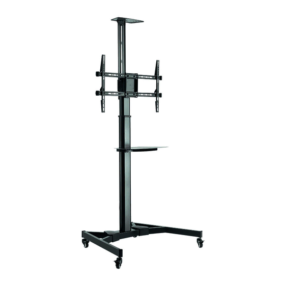
DESCRIPTION Adjustable stand for 37" to 70" (94 to 178 cm) TV. DVD/digital TV and camera trays (included). Wheels with brakes. Cable management tube. Compatible with curved TVs. -10º/+10º vertical tilt. 90º swivel. Supplied unassembled with instructions and mounting accessories. - Dimensions: Width adjustable from 20 to 60 cm x 40 cm maximum height Compatible with VESA 600 x 400 maximum With wheels: adjustable height 129-160 cm... - Page 3 M accessories Insert the right-hand base in the central base. Align the holes on the right-hand base with the holes on the central base. Secure with the connection plate and the screws. Repeat this step for the left-hand base. Lock the wheel brakes to avoid movement during installation. Each wheel can be adjusted independently with fine adjustment.
- Page 4 Pull the pin outwards and at the same time lift the inside column, until the inside column is at the height required and release the pin to secure it. Fix the universal plate to the column with the appropriate screws - 4 -...
- Page 5 - 5 -...
- Page 6 Attach the screen to the universal plate. Tighten the four screws to attach it. Important: make sure that the screen is correctly mounted and that the screws are well tightened before letting go of the screen. 10.- Vertical tilt: Remove the two screws to turn the screen 90º in a clockwise direction. Then, tighten the two screws again to secure the screen.
- Page 7 11.- Loosen the knob to adjust the screen to the required angle and then tighten the knob to secure it. 12.- Attach the camera tray to the connection plate with the appropriate screws. Tighten all the screws using an appropriate screwdriver. - 7 -...
- Page 8 13.- Attach the connection plate to the universal plate with the appropriate screws and washers. Tighten all the screws with an Allen key. 14.- Connect the DVD tray to the holder, using the appropriate screws. Remove the screws and nuts. Attach the holder to the column with the screws and nuts.
- Page 9 15.- 16.- Pass the cables through the cable management tube. Maintenance: Check that the stand is secure and check it before use at regular intervals (at least once every three months). Please contact your supplier if you have any questions. - 9 -...
- Page 10 3.- It is essential that the stand is firmly in place on the floor to make sure that it supports the maximum weight. FONESTAR will not under any circumstances be held responsible for any damage or breakages that could occur due to the stand falling on the floor because of faults in the floor or incorrect handling.
-
Page 11: Warranty
This product has been tested and has passed the corresponding quality control prior to being put on the market. FONESTAR guarantees the suitability of the product for its specified use during a period of 2 years from the delivery date and commits itself to repair or substitute the goods as expressed in the Spanish law ‘La Ley General para la Defensa de los... - Page 12 www.fonestar.com...
Need help?
Do you have a question about the STS-4264N and is the answer not in the manual?
Questions and answers