Allett C34 EVOLUTION Operator's Manual
Hide thumbs
Also See for C34 EVOLUTION:
- Operator's manual (56 pages) ,
- Operator's manual and spare parts list (74 pages) ,
- Operator's & parts manual (63 pages)
Table of Contents
Advertisement
AM81687-A
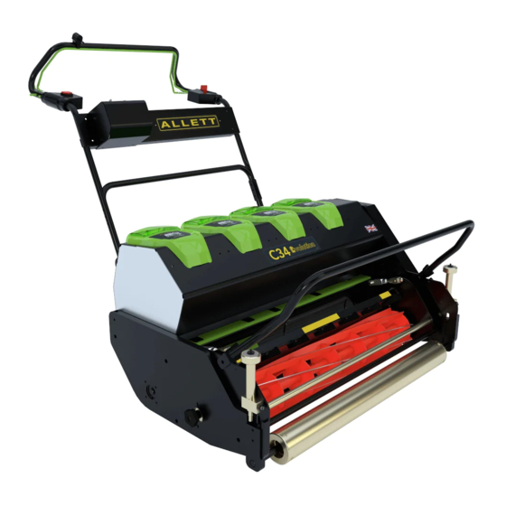
C34 EVOLUTION
Allett Limited, Regal House, Airfield Industrial Estate, Hixon, Stafford, ST18 0PF, United Kingdom
Original Instructions – English
OPERATOR MANUAL
(AM81687-A ISSUE 14/1/20)
English version
Tel: +44 (0) 1889 271503
Sales@allett.co.uk
www.allett.co.uk
For Allett spare parts
Tel: +44 (0) 1889 272095
1
Advertisement
Table of Contents

Related Manuals for Allett C34 EVOLUTION


Summary of Contents for Allett C34 EVOLUTION
- Page 1 AM81687-A C34 EVOLUTION OPERATOR MANUAL (AM81687-A ISSUE 14/1/20) English version Allett Limited, Regal House, Airfield Industrial Estate, Hixon, Stafford, ST18 0PF, United Kingdom Tel: +44 (0) 1889 271503 Sales@allett.co.uk www.allett.co.uk For Allett spare parts Tel: +44 (0) 1889 272095 Original Instructions – English...
- Page 2 AM81687-A READ THIS MANUAL BEFORE USING AN ALLETT C34 EVOLUTION BATTERY POWERED CYLINDER MOWER. YOUR SAFETY IS INVOLVED IT IS ESSENTIAL THAT OPERATORS STUDY THIS DOCUMENT FOR THEIR OWN SAFETY. Original Instructions – English...
-
Page 3: Table Of Contents
AM81687-A Contents Introduction Model type and serial number Safety notes Technical data Operating controls Batteries and charging Checking battery capacity Battery features Charging the battery Inserting the battery into the mower Removing the battery from the mower Battery connection Usage time Battery and charger recommendations Starting and stopping Starting... -
Page 4: 1.0 Introduction
AM81687-A 1.0 Introduction The C34 Evolution is designed predominantly as a lawn mower. However, the base unit has the ability to accept a range of interchangeable cartridges to cover a number of professional turf management tasks. The base unit is powered by two 72-82V 1000W brushless DC motors. One motor powers the land roll and a second powers the interchangeable cartridge via a toothed timing belt drive. -
Page 5: Safety Notes
AM81687-A Safety Notes Important! Warning! Read these instructions carefully, be familiar with the controls and the proper use of the lawnmower. Keep these instructions for future reference. Explanation of symbols on the lawnmower: General hazard safety alert Read instruction manual Beware of thrown or flying objects Keep bystanders at a safe distance from machine Switch off and remove isolation key before adjusting, cleaning and before leaving the... - Page 6 AM81687-A Battery loading position Key / Disabling device Height of cut decal ON “1” Land drive speed control OFF “0” Guard missing – Park brake Cylinder operation Electrical hazard entanglement hazard Cutter & Roller control box Never allow people unfamiliar with these instructions to use the lawnmower Local regulations may restrict the age of the operator.
-
Page 7: Technical Data
Keep all nuts, bolts and screws tight to be sure that the lawnmower is in safe working condition. Check the grass catcher frequently for wear or deterioration. Replace worn or damaged parts for safety. Ensure replacement parts fitted are approved Technical Data Designation: C34 Evolution Cylinder lawnmower Machine type C34E/1 Rated power 2 x 1000W... -
Page 8: Operating Controls
AM81687-A Operating controls ③ ④ ① ② ⑤ ⑥ 1) Cylinder engagement switch 2) Cylinder bale bar 3) Roller slow mode switch 4) Roller drive bale bar 5) Roller drive speed lever ⑦ 6) Park brake 7) Grass box 8) Grass box cradle 9) Height of cut adjuster 10) Cartridge securing screw 11) Kick stand... -
Page 9: Batteries And Charging
AM81687-A ⑮ ⑯ ⑭ 14) Battery/battery gauge 15) Cylinder to bottom blade adjusters 16) Cartridge drive coupling Batteries & Charging Checking battery capacity <35% 35-75% >75% Press the battery capacity indicator button. The lights will illuminate according to the battery’s capacity level. -
Page 10: Battery Features
AM81687-A Battery features Bluetooth function LED Fault LED The RED fault LED will illuminate and flash if the battery is over or under temperature. The battery will not work until the temperature returns to normal. Move the battery pack to a position where the air temperature is above 5°C or below 52°C. -
Page 11: Inserting The Battery Into The Mower
AM81687-A The charger used is a diagnostic charger. The Charger LED Lights will illuminate in a specific order to communicate the current battery status. They are as follows: LED Status Description Blinking Green Charging Solid Green Fully charged Solid red Over temperature Blinking red Charging fault... -
Page 12: Removing The Battery From The Mower
AM81687-A Removing the battery from the mower 1. Press and hold the battery release button 2. Remove the battery from the dock ① ② Battery connection IMPORTANT WARNING The mower can operate on a single battery if necessary. One battery may be replaced with a fully charged unit if required, all 4 batteries do not need to be replenished at the same time. -
Page 13: Usage Time
The batteries are protected from cross charging by a 7.5A fast blow fuse, this will prevent any damage or an unsafe condition occurring should the advice above not be followed. If this fuse fails it must be replaced with a fuse of a similar rating. Please use Allett part reference AM81723 as a replacement. -
Page 14: Starting And Stopping
AM81687-A Starting & Stopping Starting Turn the key switch / disabling device clockwise to position “1”. The red LED will illuminate. An audible click can be heard this is the contactor powering up the high voltage circuit. Stopping & Disabling device The key switch cuts power to the motor controllers. -
Page 15: Cylinder Controls
AM81687-A Cylinder controls Starting & Stopping the cylinder ① ② Starting: 1) Press and hold the safety button 2) Move the cylinder bale bar towards the handle. The cylinder will start to rotate Stopping: Release the cylinder bale bar and the cylinder will stop. Selecting cylinder modes Cylinder Cylinder... -
Page 16: Land Drive Controls
AM81687-A The following table lists the cylinder operational modes that can be selected: Cylinder mode Back lap Built in back lapping function if optional safety back lapping switch is purchased Cylinder fast speed Use for wet, dense or heavy grass Cylinder slow speed Use for light dry grass Cylinder reverse... -
Page 17: Selecting Slow Mode
AM81687-A Selecting slow mode >> For easy and controlled turns press the handle bar mounted SLOW MODE SWITCH. The green LED will illuminate to notify you that Slow mode has been engaged. This slows the mowers forward speed allowing you to make a controlled turn. To return to normal forward speed for mowing press the slow mode switch again. - Page 18 AM81687-A Height of cut adjustment The height of cut is set by altering the position of the front roller. Two adjusters are provided to level the front roller. Turn the height of cut adjustment knob clockwise to lower the height of cut Turn the height of cut adjustment knob anti-clockwise to raise the height of cut Use of the height bar It is recommended to use a height bar to accurately measure the height of cut on each side of the...
-
Page 19: Height Of Cut
AM81687-A Rear roller Cutting cylinder Front roller Bottom blade Height of cut Height bar For all other turf maintenance cartridges: 1) Adjust and lock the bolt on the height setting bar to your desired working height or depth 2) Tilt the mower back and wedge securely 3) With the height setting bar near one edge of the cartridge, position one end against the rear roller 4) Adjust the front roller so that it contacts the height setting bar and the head of the bolt lines up with the blade/tine/bristle... -
Page 20: Changing A Cartridge
AM81687-A Changing a cartridge ③ ④ ① ② WARNING: When the cartridge has been removed the lawn mower can tip back. Use the kick stand provided to prevent an accident. WARNING: Always remove the Key / Disabling device from the mower before changing a cartridge WARNING: Blades are sharp always wear gloves and appropriate foot wear To remove a cartridge, proceed as follows: 1) Remove the key / disabling device &... -
Page 21: Backlapping (Option)
AM81687-A Back-lapping (option) Use back lapping sparingly to correct a chipped or slightly damaged blade. Back-lapping should not replace a regular regrind at an authorised Allett dealer ① ② ③ 1) Turn the cylinder mode switch to the back-lap position... -
Page 22: Adjusting The Bottom Blade - Setting "On-Cut
AM81687-A Adjusting the bottom blade - setting “on cut” For grass cutting cylinder cartridges only. The bottom blade is correctly adjusted when the cutting cylinder lightly brushes the bottom blade as the cylinder is turned. Contact should be made across the full width of the bottom blade. The blades act like a pair of shears, as a test correctly adjusted blades will cleanly cut a piece of good quality writing paper across the width of the blade. -
Page 23: Bottom Blade Grinding Angles
Newly fitted bottom blades will need to be ground when bolted to the blade carrier to ensure a perfectly flat cutting edge. It is advisable that grinding/reconditioning is carried out by an authorised Allett dealer to the angles shown below. -
Page 24: Delivery Plate Fins
AM81687-A Delivery plate and fins The delivery plate on the cylinder cartridge and the grass deflector veins can be adjusted to alter the grass trajectory into the grass box. 1) Loosen the 4 delivery plate screws 2) Adjust the delivery plate up or down then tighten the screws 3) Loosen each grass deflector locking screw 4) Individually adjust the deflector left or right then tighten the screws 9.0 Vibration reduction... -
Page 25: Assembly
AM81687-A Assembly Attach the handle bar assembly to the mower using the 4 x M8 screws and the Nyloc nuts provided. Torque the fasteners to 25Nm. The cable for the park brake has been left attached to the mower for your convenience. -
Page 26: Protective Circuit And Fuses
Each number of flashes corresponds to a specific fault condition. Please make note of the number of red flashes then the orange flashes before contacting an Allett representative or authorised dealer. -
Page 27: Fault Finding And Flash Codes
AM81687-A Fault finding & Flash codes The following table gives checks and actions that you can perform if your machine does not operate correctly. If these do not identify/remedy the problem, contact your service agent. Symptom Possible cause Remedy Machine fails to The isolation key is not inserted Insert isolation key &... - Page 28 AM81687-A FAULT DESCRIPTION FAULT FAULT EFFECTS CODE CODE ORANGE Severe undervoltage If the current draw of the motor is very high the voltage will drop causing this warning Undervoltage cutback If the voltage drops to a very low level the controller will shut down Severe Overvoltage This can occur if the regen current is prevented from going...
-
Page 29: Disposal
AM81687-A Disposal Product, accessories and packaging should be sorted for environment-friendly recycling. The plastic components are labelled for categorised recycling. Do not dispose of electrical power tools, batteries or chargers into household waste! According to the European Directive 2002/96/EC on waste electrical and electronic equipment and 2006/66/EC on waste batteries it is EU law that power tools which are no longer suitable for use must be separately collected and sent for recovery in an environmentally-friendly manner. - Page 30 <2.5 m/s 1 m/s Technical file at: Allett Ltd, Staffordshire, ST18 0PF I hereby declare that the product described under “technical data” has been tested and found to comply with the relevant sections of the above referenced specifications. The unit complies with all essential requirements of the directives.
-
Page 31: Guarantee
Always insist on genuine Allett spares or parts. Any non-genuine parts fitted within the Warranty period will result in your manufacturing Warranty becoming null and void. Any damage caused to the product through the fitting of parts not made or approved by Allett is not covered by the guarantee. - Page 32 AM81687-A C34 EVOLUTION PARTS MANUAL Original Instructions – English...
- Page 33 AM81687-A C34E MAIN ASSEMBLIES Figure 1 ITEM NO. DESCRIPTION PART NO. QUANTITY GRASSBOX ASSEMBLY FRONT ROLLER ASSEMBLY BATTERY HOOD AND CONTROL BOX HANDLE ASSEMBLY BRAKE ASSEMBLY MAIN CHASSIS ASSEMBLY REAR ROLLER ASSEMBLY Original Instructions – English...
- Page 34 AM81687-A GRASSBOX ASSEMBLY Figure 2 ITEM NO. DESCRIPTION PART NO. QUANTITY GRASSBOX ASSEMBLY C085 C34 GRASSBOX CARRIAGE FAB C337 SET SCREW M8 x 30 SM830 WASHER M8 FORM C WM8C C34 GRASSBOX BUFFER C1733 WASHER M8 FORM A WM8A NUT M8 NYLOC Original Instructions –...
- Page 35 AM81687-A FRONT ROLLER ASSEMBLY Figure 3 ITEM NO. DESCRIPTION PART NO. QUANTITY F/ROLLER & SHAFT ASSY BSG212 LH QUICK HEIGHT ADJUSTER C094 34" ROLLER ANCHOR C1757 GRUB SCREW M8 x 8 ACGM8 SCRAPER BAR C34 C1847 WASHER M6 Form A SPRING WASHER M6 SWM6 ROLLER ANCHOR TOP HAT...
- Page 36 AM81687-A FRONT ROLLER AND SHAFT ASSEMBLY Figure 4 ITEM NO. DESCRIPTION PART NO. QUANTITY BU/C34 FRONT ROLLER FAB BSG212 C34 LI-ION F/ROLLER SHAFT C1719 BEARING 20mm 6304 2RS AM81089 20 DIA BEARING GREASE SEAL AM81596 C34 ROLLER SEAL COLLAR BSG1410 Original Instructions –...
- Page 37 TOP HANDLE ASSY C120 HANDLE BAR CROSS PANEL C1774 SWITCH ENCLOSURE MOUNT C1775 HANDLE BAR SWITCH CONSOLE ASSY C126 ALLETT MEDIUM 356 X 50 DECAL AM81621 HANDLE REINFORCEMENT C1803 SET SCREW M8 x 25 SM825 WASHER M8 FORM A NUT M8 Nyloc...
- Page 38 AM81687-A UPPER HANDLE ASSEMBLY Figure 6 ITEM NO. DESCRIPTION PART NO. QUANTITY UPPER HANDLE LOOP C1773 CYLINDER HANDLE SWITCH C125 ROLLER HANDLE SWITCH C124 CYLINDER BALE BAR ASSY C103 ROLLER BALE BAR ASSY C104 HANDLE_BOTTOM C1875 HANDLE_TOP C1874 FOAM SLEEVE C1879 SLOW SWITCH ASSY C134...
- Page 39 AM81687-A BRAKE ASSEMBLY Figure 7 ITEM NO. DESCRIPTION PART NO. QUANTITY 34" R/ROLLER F016J11595 BRAKE DISC AM81692_DISC BRAKE CALIPER AM81692_CALIPER BRAKE HUB C1841 KEY 6X6X20 FORM A AM81500 M5 X 20 SOCKET BUTTON HEAD FLANGED M5X20_SDF CALIPER BRACKET C1852 M6 X 20 SOCKET BUTTON HEAD FLANGED M6X20_SDF BRAKE CABLE C1848...
- Page 40 AM81687-A REAR ROLLER AND SCRAPER ASSEMBLY Figure 8 ITEM NO. DESCRIPTION PART NO. QUANTITY 34" R/ROLLER F016J11595 C34E REAR ROLLER SCRAPER BRACKET RHS C1846 C34E REAR ROLLER SCRAPER BRACKET LHS C1844 SCRAPER BAR C34 FRONT SCRAPER C1631 SET SCREW M6 x 20 SM620 WASHER M6 FORM C NUT M6 NYLOC...
- Page 41 AM81687-A 34” REAR ROLLER ASSEMBLY Figure 9 ITEM NO. DESCRIPTION PART NO. QUANTITY C34 LI-ION R/ROLLER SHAFT C1718 F016L12503 CENTRE DRUM ASSEMBLY F016J11599 REAR ROLLER OUTER F016J11540 BUSH F016L12497 BAR- REAR ROLLER LOCKING COLLAR BSG016 GRUB SCREW M8 x 8 ACGM8x8 DIFFERENTIAL SHAFT F016L12550...
- Page 42 AM81687-A BATTERY HOOD ASSEMBLY Figure 10 ITEM NO. DESCRIPTION PART NO. QUANTITY COVER C1764 82V BATTERY DOCK 82V BATTERY DOCK M4x20 PAN HEAD M4x20 PAN HEAD BATTERY DOCK HINGE BAR C1766 BATTERY DOCK RIB C1855 BACK LAPPING KIT C129 BATTERY DOCK CROSS BAR FAB C1769 BATTERY DOCK END COVER C1767...
- Page 43 AM81687-A MAIN CHASSIS ASSEMBLY Figure 11 ITEM NO. DESCRIPTION PART NO. QUANTITY DRIVE SIDE PLATE RHS C1714 DRIVE SIDE PLATE LHS C1713 FRONT CHASSIS RAIL FAB C392 CHASSIS RAIL FAB C391 CHASSIS CROSS BAR C1793 C34E CART LOCKING WHEEL ASSY C105 LOCATING BOSS PLATE C238...
- Page 44 AM81687-A MAIN CONTROL AND DRIVE ASSEMBLY Figure 12 ITEM NO. DESCRIPTION PART NO. QUANTITY DECK BASE LION C1788 ROLLER CONTROL BOX ASSY C115 CYLINDER CONTROL BOX ASSY C116 M6x20 SOCKET DOME FLANGE SCREW M6X20_SDF ROLLER GPE G'BOX 400RPM 112 MOTOR AM81652 CYLINDER GPE 2400RPM 112 MOTOR AM81651...
- Page 45 DRIVE ASSEMBLY AM81687-A Figure 13 ITEM NO. DESCRIPTION PART NO. QUANTITY SIDE COVER C1796 CAPTIVE NUT C1802 WASHER M10 FORM G WM10G 38T TIMING PULLEY AM81656 22T TIMING PULLEY AM81655 TIMING BELT ROLLER AM81660 TIMING BELT CYL AM81658 R/ROLLER PULLEY SPACER C1804 ROLLER MOTOR PULLEY SPACER C1827...
- Page 46 AM81687-A REAR ROLLER TENSIONER ASSEMBLY Figure 14 ITEM NO. DESCRIPTION PART NO. QUANTITY TENSIONER ARM C1799 IDLER BOSS C1794 REAR ROLLER BEARING F016L61256 HEX SET SCREW SM620 WASHER M6 NUT M6 NYLOC NNM6 M8X20 CUP SQ BOLT M820BHSS WASHER M6 FORM D WM6D SPRING WASHER M6 SWM6...
- Page 47 AM81687-A Figure 16 ITEM NO. DESCRIPTION PART NO. QUANTITY RED LED ASSY C131 GREEN LED ASSY C132 CYLINDER MODE SWITCH AM81725 KEY SWITCH C/W KEY C1785 HANDLE BAR SWITCH CONSOLE ASSY (Includes 1-4) C126 HANDLE BAR CONNECTOR CABLE ASSY C118 4 BATTERY LOOM ASSY C133 BATTERY TERMINAL ASSY...
- Page 48 AM81687-A Your nearest dealer: Allett Ltd, Regal House, Airfield Industrial estate, Hixon, Staffordshire ST18 0PF, UK AM81687-A Original Instructions – English...
Need help?
Do you have a question about the C34 EVOLUTION and is the answer not in the manual?
Questions and answers