Table of Contents
Advertisement
BY
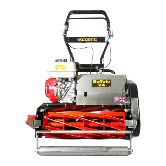
BUFFALO 20", 24" & 27"
OPERATORS & PARTS MANUAL
English version
Turfmech Machinery Limited
Hangar 5, New Road, Hixon, Stafford, ST18 0PJ, United Kingdom
Tel: +44 (0) 1889 271503
Fax: +44 (0) 1889 271321
sales@turfmech.co.uk
www.turfmech.co.uk
For Allett spare parts
Tel: +44 (0) 1889 272092 or 272093
Fax: +44 (0) 1889 272084
sales@allett.co.uk
www.allett.co.uk
Advertisement
Table of Contents

Related Manuals for Allett BUFFALO 20"


Summary of Contents for Allett BUFFALO 20"
- Page 1 Hangar 5, New Road, Hixon, Stafford, ST18 0PJ, United Kingdom Tel: +44 (0) 1889 271503 Fax: +44 (0) 1889 271321 sales@turfmech.co.uk www.turfmech.co.uk For Allett spare parts Tel: +44 (0) 1889 272092 or 272093 Fax: +44 (0) 1889 272084 sales@allett.co.uk www.allett.co.uk...
- Page 3 ATTENTION THIS SYMBOL MEANS BE ALERT! YOUR SAFETY IS INVOLVED READ THIS MANUAL BEFORE USING AN ALLETT BUFFALO CYLINDER MOWER. IT IS ESSENTIAL THAT OPERATORS STUDY IT FOR THEIR OWN SAFETY.
-
Page 5: Table Of Contents
Contents Page Introduction…………………………………………………………………………….. 1 Model and serial number……………………………………………………….. 1 EC Conformity Information………………………………………………………….. 2 EC Declaration of Conformity………………………………………………………..3 Safety Precautions……………………………………………………………………. 4 Health and Safety at Work Act….…………………………………………….. 4 Training………………………………………………………………………….. 4 Preparation……………………………………………………………………… 5 Decal positions…………………………………………………………………. 6 Operation………………………………………………………………………... 7 Operation……...………………………………………………………………………... 9 Operator controls…………………………………………………………………9 Adjusting the handlebars……………………………………………………….. - Page 6 Monthly Maintenance………………………………………………………………. 23 Checking the chains and belts……………………………………………….. 23 6 Month Maintenance……………………………………………………………..24 Checking the spark plug………………………………………………………. 24 Yearly Maintenance………………………………………………………………… 24 Replacing the spark plug……………………………………………………… 24 Replacing the air filter elements……………………………………………… 24 Replacing the engine oil………………………………………………………. 24 Miscellaneous Maintenance……………………………………………………….. 25 Adjusting cable tensions……………………………………………………….
-
Page 7: Introduction
Introduction The Buffalo mower is a petrol engine powered, self propelled machine with a belt and chain driven differential rear roller. The cutting cylinder is belt driven. The Buffalo mower is a product of exceptional quality and is designed solely for cutting grass. -
Page 8: Ec Conformity Information
EC Conformity Information Noise levels Operator’s daily personal noise exposure: Turfmech Machinery Limited has no control over site conditions, duration of use, level of maintenance or adjustment of the Buffalo. All of these factors will affect the operator’s daily personal noise exposure level (L EP,d Under typical working conditions operators could be exposed to a daily personal noise exposure level in excess of 98 dB(A) L... -
Page 9: Ec Declaration Of Conformity
EC Declaration of Conformity Turfmech Machinery Limited, Hangar 5, New Road, Hixon, Staffordshire, ST18 0PJ, England declare that the grass mowing equipment: Model Buffalo mower Category Pedestrian controlled turf mower Type Cylinder Engine Manufacturer Honda Speed of rotation 3000 RPM Complies with the provisions of Directive 2006/42/EC Essential Health and Safety Requirements Relating to the Design and Construction of Machinery and Safety Components. -
Page 10: Safety Precautions
(e.g. engine manual), which have been found necessary as a result of the research and testing of Turfmech Machinery Limited and Allett. Training READ THIS MANUAL BEFORE USING THE BUFFALO MOWER. IT IS ESSENTIAL THAT OPERATORS STUDY IT FOR THEIR OWN SAFETY. -
Page 11: Preparation
Preparation While operating the equipment always wear substantial footwear and long trousers. Do not operate the equipment when barefoot or wearing open sandals. Ear protection should be worn when the engine is running. Eye protection should be worn whilst mowing. Thoroughly inspect the area that is to be cut and remove all objects which are likely to cause damage to the machine. -
Page 12: Decal Positions
Decal Positions Description Large Allett logo Location Grass box Quantity Description Small Allett logo Location front plate on the handle bars Quantity Description Blade adjuster information Location Above LH/RH bottom blade adjusting bolts Quantity Description Blade hazard decal Location Centre of grass deflector... -
Page 13: Operation
Safety Notice Operation Do not operate the engine in a confined space where dangerous carbon monoxide fumes can collect. Mow only in daylight or in good artificial light. Before starting the engine, disengage drive to the cutting cylinder and the rear drive roller and engage the parking brake. - Page 14 ALWAYS KEEP HANDS AND FEET WELL AWAY FROM A ROTATING CUTTING CYLINDER. IF IN DOUBT ABOUT THE SAFE OPERATION OR MAINTENANCE OF YOUR ALLETT MOWER, CONTACT TURFMECH MACHINERY LTD OR YOUR AUTHORISED ALLETT DEALER. Remember – a careful operator who uses common sense is the safest...
-
Page 15: Operation
Operation Operator controls 1. Parking brake 2. Cutting cylinder drive clutch 3. Handlebar 4. Rear roller drive clutch 5. On/off switch. 6. Throttle control Adjusting the handle bars Loosen the four bolts at the base of the upper • handle bar. Move the handle bar into the desired position •... -
Page 16: Starting The Engine
Starting the engine Before starting the engine: Ensure that the drives to the rear roller and cutting cylinder are disengaged. • Check that the parking brake is engaged. • Check that the engine switch and • handlebar switches are in the ON position. -
Page 17: Engaging Forward Travel
Engaging forward travel Start the engine. • Set the engine to approx ¼ throttle. • Push the drive clutch fully forwards with the right • hand. Travel speed depends on engine speed. Adjust the • travel speed by adjusting the engine throttle lever to the desired position. -
Page 18: Cleaning The Mower
Cleaning the mower When cleaning the mower avoid pressure washing. Use low pressure water or compressed air. After pressure washing it is important that the cylinder bearings are purged of water. This can be done by applying a small amount of grease using a hand pump. Note that over-greasing will damage the seals. - Page 19 The adjusters alter the gap between the bottom blade • and the cutting cylinder. Rotate the adjuster clockwise to increase the gap. Rotate the adjuster anti-clockwise to decrease the gap. Clockwise Anti-clockwise Adjust the clearance between the bottom blade and the cutting cylinder so •...
-
Page 20: Cylinder And Bottom Blade Grinding/Reconditioning
It is advised that the grinding / reconditioning of the cylinder and bottom blade be carried out by either Turfmech Machinery Limited or an authorised Allett dealer. The bottom blade of this machine should be ground at zero degrees to the horizontal. -
Page 21: Adjusting The Height Of Cut
WARNING - PREVENT ACCIDENTS Always wear suitable safety gloves when working with the blade and cylinder. Adjusting the height of cut Always set the bottom blade to the correct position before attempting to set the • height of cut. The height is set using the setting bar provided. The bolt on this should be •... -
Page 22: Maintenance
Correct servicing will prolong the working life of the machine and safeguard the warranty. Always fit genuine Allett parts, fitting spurious parts will invalidate the warranty. The following information is given on the understanding that Turfmech Machinery Limited accepts no responsibility for work carried out by a customer or for any damage thus caused, whether or not the service instructions have been misunderstood. - Page 23 WARNING - PREVENT ACCIDENTS Use hazardous substances carefully. The following fluids are identified as being hazardous: Substance Risk Grease Petrol High It is recommended that eye protection and gloves are worn when handling the above fluids and that care is taken to avoid spillages. Avoid contact with skin –...
-
Page 24: Maintenance Schedule
Maintenance Schedule Months Yearly Activity Task Daily Weekly Monthly hours Check Engine oil level ● Air cleaner condition ● Fuel level ● Guards in place ● Tyre pressures (if fitted) ● Cutting cylinder/blade ● Fasteners ● Chain and belt tension ●... -
Page 25: Daily Checks / Maintenance
Daily Checks / Maintenance Checking engine oil level The level of the engine oil should be checked • when the engine at rest, cool and on level ground. Locate the engine oil dipstick at the front of • the engine. Remove it and wipe clean. -
Page 26: Checking The Fuel Level
Poorly maintained parts will lead to a poor quality of cut. It is advised that the grinding / reconditioning of the cylinder and bottom blade • be carried out by either Turfmech Machinery Limited or an authorised Allett dealer. -
Page 27: Testing The Parking Brake
WARNING - PREVENT ACCIDENTS If the engine does not stop – DO NOT USE THE MACHINE – contact your • Turfmech/Allett dealer. Carry out the same procedure for the on/off switch on the engine. •... -
Page 28: Weekly Maintenance
Weekly Maintenance Check fastener torques Ensure that the engine is switched off and the cutting • cylinder is stationary. Check and where necessary tighten the bearing • retaining fasteners. Check and where necessary tighten the belt and • chain tensioner fasteners. Check and where necessary tighten the engine and •... -
Page 29: Cleaning The Air Filter Element
Cleaning the air filter element Remove the air filter element from its housing (see p19). • To clean the inner paper element, use a compressed air supply to blow out the • dust. Take care not to damage the element whilst cleaning it. To clean the outer foam element, wash it in warm soapy water. -
Page 30: Month Maintenance
6 Monthly Maintenance Checking the spark plug condition and gap WARNING - PREVENT ACCIDENTS Allow the engine to cool before attempting to remove the spark plug. Locate the spark plug. • Pull off the high tension lead and remove • the spark plug using a spark plug socket. -
Page 31: Miscellaneous Maintenance
Locate the engine drain plug at the bottom of the engine (see p24). There are • two drain plugs, the drain plug at the rear of the machine is more accessible. Remove the dipstick. • Place a container of suitable capacity underneath the drain plug, remove the •... -
Page 32: Changing The Drive Belts
Changing the drive belts Remove the main cover in order to expose the drive • belts and chain. Remove the belt cover / guide from around the • large aluminium belt pulley. Remove the duplex drive coupling chain by undoing •... -
Page 33: Setting The Compound Sprocket
Setting the compound (lower chain) sprocket This should be carried out by Turfmech Machinery Limited or an authorised • Allett dealer. Cylinder and bottom blade servicing This should be carried out by Turfmech Machinery Limited or an authorised • Allett dealer (see p20). -
Page 34: Storage
Preparing the machine for storage Clean the machine so that it is clear of grass and any other debris. • Repair any worn or damaged parts – replace with genuine Turfmech/Allett • parts if new parts are required. Check all bolts and tighten as necessary. -
Page 35: Preparing The Engine For Storage
Preparing the engine for storage Drain the fuel. • For a small amount of fuel start the engine and allow it to run until all the fuel is • consumed. For a larger amount of fuel loosen the drain plug on the sediment bowl and •... -
Page 36: Troubleshooting
Troubleshooting Problem Possible cause Remedy Occasional blades of uncut Height of cut too high. Reduce height of cut. grass Poorly adjusted bottom blade. Re-adjust bottom blade. Blunt cutting cylinder/bottom blade. Grind/recondition as necessary. Drive belt slipping. Adjust belt tension. Strips of uncut grass Overlap between runs too small. -
Page 37: Specifications
Specifications 20” Buffalo 24” Buffalo 27” Buffalo Cutting Width 510mm (20”) 610mm (24”) 686mm (27”) Overall Width 686mm (27”) 787mm (31’) 864mm (34”) Weight 111kg (245lb) 122kg (269lb) 138kg (304lb) Engine Honda GX120 Honda GX160 Honda GX160 Overall Height 1010mm (40”) Overall Length 1280mm (50”) Rate of Cut... -
Page 39: Parts Section
BUFFALO 20, 24 & 27 PARTS SECTION... -
Page 41: Parts Manual
Parts Manual Contents Chassis………………………………………………………………………………………………………. Cutting Cylinder, Bottom Blade and Front Roller……………………………………………………….. Engine and Drive Shaft…………………………………………………………………………………….. Drive Train Components…………………………………………………………………………………… Parking Brake……………………………………………………………………………………………….. Handlebars and Control Cables…………………………………………………………………………... Rear Drive Roller…………………………………………………………………………………………… Grassbox………………………………………………………………………………………………….. -
Page 42: Chassis
Chassis... - Page 43 Chassis Item No Description Part No Part No Part No Buffalo 20 Buffalo 24 Buffalo 27 Grommet PVC AM81264 AM81264 AM81264 Tunnel Guard BSG1125 BSG1126 BSG1127 Nameplate (20” shown) BSG1174 BSG1175 BSG1176 Nameplate “Buffalo” BSG1171 BSG1171 BSG1171 Label warning rear roller (LH thread) AM81037 AM81037 AM81037...
-
Page 44: Cutting Cylinder, Bottom Blade And Front Roller
Cutting Cylinder, Bottom Blade and Front Roller... - Page 45 Cutting Cylinder, Bottom Blade and Front Roller Item No Description Part No Part No Part No Buffalo 20 Buffalo 24 Buffalo 27 Label - cylinder and blade warning AM81263 AM81263 AM81263 Set screw M6 x 20 SM620 SM620 SM620 Washer spring M6 SWM6 SWM6 SWM6...
- Page 46 Cutting Cylinder, Bottom Blade and Front Roller...
- Page 47 Cutting Cylinder, Bottom Blade and Front Roller Item No Description Part No Part No Part No Buffalo 20 Buffalo 24 Buffalo 27 Set screw 3/8 UNF x 1 S11014 S11014 S11014 Bearing 25mm flanged AM81009 AM81009 AM81009 Cylinder Buffalo 8 blade AB014/8 AB015/8 AB016/8...
-
Page 48: Engine And Drive Shaft
Engine and Drive Shaft... - Page 49 Engine and Drive Shaft Item No Description Part No Part No Part No Buffalo 20 Buffalo 24 Buffalo 27 Washer M8 Washer spring M8 SWM8 SWM8 SWM8 Set screw M8 x 35 SM835 SM835 SM835 Honda engine GX120 GX160 GX160 Key –...
-
Page 50: Drive Train Components
Drive Train Components... - Page 51 Drive Train Components Item No Description Part No Part No Part No Buffalo 20 Buffalo 24 Buffalo 27 Set screw M6 x 45 SM645 SM645 SM645 Cable retaining plate AB008 AB008 AB008 Washer M6 Spring AM90519 AM90519 AM90519 Cable anchor plate BSG012 BSG012 BSG012...
- Page 52 Drive Train Components...
- Page 53 Drive Train Components Item No Description Part No Part No Part No Buffalo 20 Buffalo 24 Buffalo 27 Chain tensioner sleeve BSG1038 BSG1038 BSG1038 Washer M10 Form G WM10G WM10G WM10G Chain 3/8 “ AM81054 AM81054 AM81054 Nut Nylock 5/16 UNF N11003 N11003 N11003...
- Page 54 Drive Train Components...
- Page 55 Drive Train Components Item No Description Part No Part No Part No Buffalo 20 Buffalo 24 Buffalo 27 Belt engine drive Buffalo (20” shown) AM89482 AM89482 AM89482 Set screw 3/8 UNF x 1 S11014 S11014 S11014 Washer spring M10 SWM10 SWM10 SWM10 Washer M10...
-
Page 56: Parking Brake
Parking Brake... - Page 57 Parking Brake Item No Description Part No Part No Part No Buffalo 20 Buffalo 24 Buffalo 27 Handle grip AM81140 AM81140 AM81140 Brake lever BSG045 BSG045 BSG045 Nut Nylock M6 NNM6 NNM6 NNM6 Set screw M6 x 25 SM625 SM625 SM625 Set screw M6 x 20 SM620...
-
Page 58: Handlebars And Control Cables
Handlebars and Control Cables... - Page 59 Handlebars and Control Cables Item No Description Part No Part No Part No Buffalo 20 Buffalo 24 Buffalo 27 Yoke anchor point BSG1024 BSG1024 BSG1024 Set screw M6 x 20 SM620 SM620 SM620 Washer nylon M6 AM81093 AM81093 AM81093 Lever mounting spigot BSG1081 BSG1081 BSG1081...
- Page 60 Handlebars and Control Cables...
- Page 61 Handlebars and Control Cables Item No Description Part No Part No Part No Buffalo 20 Buffalo 24 Buffalo 27 Label – Allett 9” AM81030 AM81030 AM81030 Set screw M10 x 20 SM1020 SM1020 SM1020 Set screw M8 x 16 SM816...
-
Page 62: Rear Drive Roller
Rear Drive Roller... - Page 63 Rear Drive Roller Item No Description Part No Part No Part No Buffalo 20 Buffalo 24 Buffalo 27 Set screw M6 x 20 SM620 SM620 SM620 Washer spring M6 SWM6 SWM6 SWM6 Washer M6 Brake cable retainer BS1002 BS1002 BS1002 Spring AM90519 AM90519...
- Page 64 Rear Drive Roller...
- Page 65 Rear Drive Roller Item No Description Part No Part No Part No Buffalo 20 Buffalo 24 Buffalo 27 Rear roller lock collar BSG016 BSG016 BSG016 Differential centre BSG024 BSG024 BSG024 Pinion gear steel BSG1101 BSG1101 BSG1101 Key – 1/4 x 1-1/4 AM92888 AM92888 AM92888...
-
Page 66: Grassbox
Grassbox... - Page 67 Buffalo 24 Buffalo 27 Grassbox swivel BSG013 BSG013 BSG013 Grassbox swivel bush BSG1050 BSG1050 BSG1050 Grassbox plate BSG1029 BSG1029 BSG1029 Label – Allett 15” AM81031 AM81031 AM81031 Grassbox Buffalo AM89511 AM89510 AM92510 Grassbox stiffener BSG006 BSG1021 BSG1022 Grassbox arm RH BSG1068...
-
Page 68: Notes
Notes...
Need help?
Do you have a question about the BUFFALO 20" and is the answer not in the manual?
Questions and answers