Allett C 34 Operator's Manual And Spare Parts List
Hide thumbs
Also See for C 34:
- Operator's manual (56 pages) ,
- Operator's manual (48 pages) ,
- Operator's & parts manual (63 pages)

Related Manuals for Allett C 34


Summary of Contents for Allett C 34
- Page 1 OPERATORS & PARTS MANUAL English version Turfmech Machinery Limited Hangar 5, New Road, Hixon, Stafford, ST18 0PJ, United Kingdom Tel: +44 (0) 1889 271503 Fax: +44 (0) 1889 271321 Sales@allett.co.uk www.allett.co.uk...
- Page 3 ATTENTION THIS SYMBOL MEANS BE ALERT! YOUR SAFETY IS INVOLVED READ THIS MANUAL BEFORE USING AN ALLETT C34 CYLINDER MOWER. IT IS ESSENTIAL THAT OPERATORS STUDY IT FOR THEIR OWN SAFETY.
-
Page 4: Table Of Contents
Contents Introduction ....................6 Model type and serial number............... 6 EC conformity information ................7 EC Declaration of Conformity ............... 8 Safety Precautions..................9 Training ....................9 Preparation ..................10 Operation .................... 11 Maintenance and storage ..............12 Decal positions .................... 13 Operation –... - Page 5 Check fastener torques ............33 Cleaning the fuel sediment bowl ..........33 Bi-weekly maintenance ............... 34 Checking the chains and belts ..........34 Yearly maintenance ................35 Replacing the spark plug ............35 Replacing air filter elements ............. 35 Replacing the engine oil ............35 Miscellaneous maintenance ...............
-
Page 6: Introduction
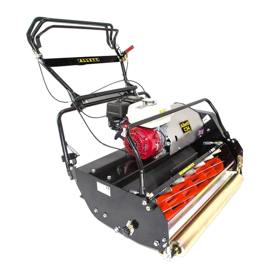
Introduction The C34 mower is a petrol engine powered self propelled machine with a belt and chain driven differential rear roller and a belt driven cutting cylinder. The C34 mower is a product of exceptional quality and is designed solely for cutting high quality turf. -
Page 7: Ec Conformity Information
EC conformity information Noise levels Operator’s daily personal noise exposure: Turfmech Machinery Limited has no control over site conditions, duration of use, state of maintenance or adjustment of the SQRL. All of these factors will affect the operator’s daily personal noise exposure level EP,d Under typical working conditions operators could be exposed to a daily personal noise exposure level in excess of 98 dB(A) L... -
Page 8: Ec Declaration Of Conformity
EC Declaration of Conformity Turfmech Machinery Limited, Hangar 5, New Road, Hixon, Staffordshire, ST18 0PJ, England declare that the off-highway pedestrian controlled debris collection equipment: Model Category Pedestrian controlled fine turf mower Type Cylinder Engine Manufacturer Honda Speed of rotation 3600 RPM Complies with the provisions of Directive 98/37/EC Essential Health and Safety Requirements Relating to the Design and Construction of Machinery and Safety Components. -
Page 9: Safety Precautions
Safety Precautions Training READ THIS MANUAL BEFORE USING THE C34 MOWER. IT IS ESSENTIAL THAT OPERATORS STUDY IT FOR THEIR OWN SAFETY. THE FOLLOWING PRECAUTIONS MUST BE TAKEN TO HELP PREVENT ACCIDENTS. A CAREFUL OPERATOR WHO USES COMMON SENSE IS THE SAFEST OPERATOR. Read the instructions carefully. -
Page 10: Preparation
Preparation While operating the equipment always wear substantial footwear and long trousers. Do not operate the equipment when barefoot or wearing open sandals. Ear protection should be worn when the engine is running. Eye protection should be worn whilst mowing. Thoroughly inspect the area that is to be cut and remove all objects which are likely to cause damage to the machine. -
Page 11: Operation
Operation Do not operate the engine in a confined space where dangerous carbon monoxide fumes can collect. Mow only in daylight or in good artificial light. Before starting the engine, disengage drive to the cutting cylinder and the rear drive roller and engage the parking brake. -
Page 12: Maintenance And Storage
This is, however, subject to the equipment being properly used and maintained according to the conditions stated in this manual and elsewhere, which have been found necessary as a result of the research and testing of Turfmech Machinery Limited and Allett. -
Page 13: Decal Positions
Decal positions Description - Large Allett logo Location - Grass box Quantity Description - Small Allett logo Location - Handle bars Quantity... -
Page 14: Operation - Base Machine
Operation – base machine SAFETY NOTICE WARNING - PREVENT ACCIDENTS Before operating the C34 mower it is essential that: The operator reads and understands this manual. The daily maintenance checks have been properly carried out and the equipment is in good working order. -
Page 15: Adjusting The Handle Bars
Adjusting the handle bars Loosen the four bolts • at the base of the upper handle bar. Move the handle bar • into desired position. Tighten the four bolts. • Parking brake To engage the parking brake, pull the red lever •... -
Page 16: Stopping The Engine
Switch the on/off switch on the handle bars to ON. • Check that the engine on/off switch is set to ON. • Set the engine throttle to the half way position. • Ensure that the fuel shut-off off tap (2) is set to the ON position. •... -
Page 17: Engaging Forward Travel
Engaging forward travel Start the engine. • Set the engine throttle to the half way position. • Push the drive clutch forwards. • Travel speed depends on engine speed. Adjust the travel • speed by adjusting the engine throttle lever to the desired position. -
Page 18: Loading A Driven Cartridge
Loading a driven cartridge Before loading the cartridge ensure that the • locking knob on the side of the mower chassis is loosened off by rotating it anti-clockwise. Carefully lift the cartridge using the two red • handles and then lower it onto the support rails on the inside of the mower chassis. -
Page 19: Operation - Cartridges
Operation – cartridges SAFETY NOTICE WARNING - PREVENT ACCIDENTS Always wear the correct personal protective equipment when operating the C34 mower: Overalls. Heavy boots. Safety glasses. Ear protection. WARNING - PREVENT ACCIDENTS Never clean/unblock the mower when the engine is running. Always stop the engine, engage the parking brake and wait until the cylinder has completely stopped rotating. -
Page 20: Cleaning The Mower
Cleaning the mower When cleaning the mower avoid pressure washing. Use low pressure water or compressed air. After pressure washing it is important that the cylinder bearings are purged of water. This can be done by applying a small amount of grease using a hand pump. Note that over-greasing will damage the seals Damage caused by over greasing is not covered by the Turfmech Machinery Limited warranty. - Page 21 The adjusters alter the gap between the bottom blade and the • cutting cylinder. Rotate the adjuster clockwise to increase the gap. Rotate the adjuster anti-clockwise to decrease the gap. Clockwise Anti-clockwise Adjust the clearance between the bottom blade and the cutting cylinder so that the paper is •...
- Page 22 WARNING - PREVENT DAMAGE. Do not over tighten – the cylinder should be able to spin freely. If you are still unable to cleanly cut the paper, inspect the bottom blade and cylinder. If they • appear rounded or damaged they may need to be sharpened. WARNING - PREVENT DAMAGE.
-
Page 23: Adjusting The Height Of Cut
Adjusting the height of cut Always set the bottom blade to the correct position before attempting to set the height of cut. • The height is set using the setting bar provided. The bolt on this should be adjusted until it reaches •... - Page 24 To adjust the position of the front roller: • Locate the roller adjusters, these can be found at the front of the machine on each side of the chassis. The front roller height can be altered with these adjusters. Rotate clockwise to reduce the height of cut and anti-clockwise to increase the height of cut.
-
Page 25: Cylinder And Bottom Blade Grinding/Reconditioning
Poorly maintained parts will lead to a poor quality of cut. It is advised that the grinding /reconditioning of the cylinder and bottom blade be carried out by either Turfmech Machinery Limited or a registered Allett dealer. Operation – other cartridges... -
Page 26: Maintenance Schedule
Maintenance schedule Yearly Activity Task Daily Weekly Bi-weekly 500 hours Check Engine oil level ● Air cleaner condition ● Fuel level ● Guards in place ● Tyre pressures (if fitted) ● Cutting cylinder ● Fasteners ● Chain and belt tension ●... -
Page 28: Maintenance
Regular maintenance is essential for the continued safe operation of the C34 mower. Correct servicing will prolong the working life of the machine and safeguard the warranty. Always fit genuine Allett parts, fitting spurious parts will invalidate the warranty. The following information is given on the understanding that Turfmech Machinery Limited accepts no responsibility for work carried out by a customer or for any damage thus caused, whether or not the service instructions have been misunderstood. - Page 29 IMPORTANT – PREVENT ENVIRONMENTAL DAMAGE When disposing of hazardous waste products, take them to an authorised disposal site. Waste products must not be allowed to contaminate surface water, drains or sewerage systems.
-
Page 30: Daily Checks/Maintenance
Daily checks/maintenance Checking engine oil level The level of the engine oil should be checked when the • engine is at rest and cool. Locate the engine oil dipstick at the front of the engine. • Remove it and wipe clean. •... -
Page 31: Checking Belt/Chain Guards
Poorly maintained parts will lead to a poor quality of cut. It is advised that the grinding/reconditioning of the cylinder and bottom blade be carried out by • either Turfmech Machinery Limited or a registered Allett dealer. Testing the parking brake WARNING - PREVENT ACCIDENTS Carry out this check in a well ventilated area clear of obstacles and bystanders. -
Page 32: Testing The Ignition On/Off Switches
Once the engine is running turn the on/off switch on the handlebars to the OFF position, the engine • should stop immediately. WARNING - PREVENT ACCIDENTS If the engine does not stop – DO NOT USE THE MACHINE – contact your Turfmech/Allett dealer. • Carry out the same procedure for the on/off switch on the engine. •... -
Page 33: Weekly Maintenance
Weekly maintenance Check fastener torques Ensure that the engine is switched off and the cutting cylinder is • stationary. Check and where necessary tighten the bearing retaining • fasteners. Check and where necessary tighten the belt and chain tensioner • fasteners. -
Page 34: Bi-Weekly Maintenance
Bi-weekly maintenance Checking the spark plug condition and gap WARNING - PREVENT ACCIDENTS Allow the engine to cool before attempting to remove the spark plug. Locate the spark plug. • Pull off the high tension lead and remove the spark •... -
Page 35: Yearly Maintenance
Yearly maintenance Replacing the spark plug Remove the spark plug as described in the bi-weekly maintenance section. • Fit the new spark plug. • Start the engine and ensure that it runs smoothly before carrying out any further maintenance. • Replacing air filter elements Remove the air filter elements –... -
Page 36: Miscellaneous Maintenance
Miscellaneous maintenance Adjusting cable tensions Fine adjustments can be made as described below: Locate the in-line adjuster on the cable. • Loosen the locking nut. • Adjust the cable tension as necessary by • rotating the adjuster. When the cable tension is correct tighten the lock nut. •... -
Page 37: Storage
Preparing the machine Clean the machine so that it is clear of grass and any other debris. • Repair any worn or damaged parts – replace with genuine Turfmech/Allett parts if new parts are • required. Check all bolts and tighten as necessary. -
Page 38: Removing From Storage
Removing from storage Carry out the daily inspection list. • Open the fuel shut-off tap. • Check tyre pressures (where fitted). •... -
Page 39: Troubleshooting
Troubleshooting Problem Possible cause Remedy Occasional blades of uncut Engine speed too slow. Increase engine speed. grass. Ground speed too fast. Reduce forward travel speed. Height of cut too high. Reduce height of cut. Poorly adjusted bottom blade. Re-adjust bottom blade. Blunt cutting cylinder/bottom blade. -
Page 40: Specification - Base Machine
Specification – Base machine Cutting Width 34" Engine Honda GX200 6.5 hp Overall Width 1168mm Weight 164kg Overall Length 1775mm Overall Height 1020mm Drive Clutch Handle mounted lever operating twin V-belts via a cable. Cutter Clutch Handle mounted lever operating triple V-belts via a cable. Driver Roller Three section rubberised steel with steel bevel gear differential Groomer Adjustment... -
Page 41: Specification - Cartridges
Specification – Cartridges Weight Working Width Overall Width 34" Scarifier 29kg 863mm 978mm 24" Verticutter 30kg 863mm 978mm 34" Brush 25kg 863mm 978mm Cutting rates 6 Blade 94 Cuts per metre (86 cuts per yard) (2.39 cuts per inch) 8 Blade 125 Cuts per metre (114 cuts per yard) (3.18 cuts per inch) - Page 43 PARTS SECTION...
- Page 45 COUNTERSHAFT HANDLE BAR ENGINE SIDE ASS’Y ASS’Y LOWER HANDLE BAR KICKSTAND ASS’Y ASS’Y HONDA MAINFRAME ENGINE GX200 ASS’Y COUNTERSHAFT BRAKE SIDE ASS’Y FRONT ROLLER ASS’Y REAR ROLLER ASS’Y GRASSBOX ASS’Y...
-
Page 46: Model C34:- Front Roller Assembly Bom (Fig 1)
MODEL C34:- Front Roller Assembly BOM (FIG 1) ITEM DESCRIPTION PART NUMBER USED CUP SQ BOLT ZINC M8X25 BM8X25 CUP SQ NUT NYLOC M8 NM8 NYLOC WASHER M8 FRONT ROLLER PLAIN 34” BSG1267 FRONT ROLLER SHAFT 34” C1582 BEARING 20mm AM81007 LOCKING COLLAR BG003... -
Page 47: Model C34:- Countershaft Assembly Engine Side Bom (Fig 2A)
NUT PLAIN M8 SET SCREW M8X25 M825 G/BOX LOCATOR FAB C320 HEIGHT SETTING BAR C1598 GRASSBOX C34 C1556 REINFORCING PLATE C1593 R.H GRASS BOX ARM C1592 L.H GRASSBOX ARM C1591 DECAL – ALLETT LARGE AM81545 34" B GRASSBOX STIFFENER C1590 FIG 2... - Page 48 MODEL C34:- Countershaft Assembly Engine Side BOM (FIG 3A) ITEM DESCRIPTION PART NUMBER USED C34" TUNNEL GUARD C1600 DECAL ALLETT AM81549 DECAL C AM81550 DECAL 34 AM81553 SET SCREW M6X20 SM620 PLAIN WASHER M6 PLAIN NUT M6 ROLLER DRIVE SHAFT...
- Page 49 MODEL C34:- Countershaft Assembly Engine Side...
-
Page 50: Model C34:- Countershaft Assembly Brake Side Bom (Fig 2B)
MODEL C34:- Countershaft Assembly Brake Side BOM (FIG 3B) ITEM DESCRIPTION PART NUMBER USED CABLE RETAINING PLATE AB008 PLAIN WASHER M6 SET SCREW M6X35 SM635 SET SCREW M6X45 SM645 PLAIN WASHER M6 FORM G WM6G PIVOT FERRULE C1570 SET SCREW M6X12 SM612 YOKE ANCHOR POINT BSG1024... - Page 51 MODEL C34:- Counter Assembly Brake Side...
-
Page 52: Model C34:- Kickstand Assembly Bom (Fig 3)
MODEL C34:- Kickstand Assembly BOM (FIG 4) ITEM DESCRIPTION PART NUMBER USED PLAIN NUT M8 STAY MOUNT BRKT FAB C323 PLAIN NUT M6 SPRING RT-00003098 SET SCREW M6X25 M625 SET SCREW M8X25 M825 SET SCREW M6X35 M635 SET SCREW M8X45 M845 PLAIN WASHER M8 NUT NYLOC M8... - Page 53 MODEL C34:- Kickstand Assembly...
-
Page 54: Model C34:- Handle Bar Assembly Bom (Fig 4)
BSG1024 NUT NYLOC M6 NNM6 ROLLER DRIVE CABLE BSG1078 CUTTER CLUTCH CABLE BSG1077 BRAKE CABLE BSG1088 THROTTLE CABLE AM89500 DECAL- ALLETT SMALL AM81543 1-21 TOP HANDLE FAB COMPLETE BSG092 GROMMET PVC* AM81264 CABLE TIES* AM81068 ON/OFF SWITCH HARNESS ASSY* BSG035... - Page 55 MODEL C34:- Handle Bar Assembly...
-
Page 56: Model C34:- Lower Handle Bar Assembly Bom (Fig 5)
MODEL C34:- Lower Handle Bar Assembly BOM (FIG 6) ITEM DESCRIPTION PART NUMBER USED A/V BOTTOM HANDLE FAB C312 SET SCREW M10X25 SM1025 WHEEL CLAMP WASHER AC4246 UNIVERSAL MOUNT AM81320 LH PIVOT BRAKCET BSG110 NUT NYLOC M10 NNM10 PLAIN NUT M10 NM10 SET SCREW M8X25 M825... - Page 57 MODEL C34:- Lower Handle Bar Assembly...
-
Page 58: Model C34:- Rear Roller Assembly Bom (Fig 6)
MODEL C34:- Rear Roller Assembly BOM (FIG 7) ITEM DESCRIPTION PART NUMBER USED REAR ROLLER SHAFT C1581 DIFF. SHAFT FAB. -DUAL GEAR AB056 SET SCREW M8X25 SM825 REAR ROLLER LOCKING COLLAR BSG016 GRUB SCREW M8 x 8 ACGM8X8 BEARING 25mm - FLANGED AM81049 REAR ROLLER OUTER SECTION AB058... - Page 59 MODEL C34:- REAR ROLLER ASSEMBLY...
-
Page 60: Model C34:- Main Frame Assembly Bom (Fig 7A)
MODEL C34:- Main Frame Assembly BOM (FIG 8) ITEM DESCRIPTION PART NUMBER USED DRIVE GAURD C1580 KEY FORM A AM81500 BOTTOM BELT GUIDE FAB C319 CYLINDER PULLEY C1594 ENGINE DRIVE BELT BUFFALO AM81499 DRIVE SPINDLE C1528 BEARING HOUSING C1045 BEARING ANGULAR CONTACT AM81436 SET SCREW M12X35 SM1235... - Page 61 MODEL C34:- Main Frame Assembly FIG 8...
- Page 62 MODEL C34: BRUSH CARTRIDGE BOM (FIG 9) ITEM DESCRIPTION PART NUMBER USED SUPPORT ANGLE C1615 CARTRIDGE HANDLE C1132 END PLATE C1014 ACCESSORY DRIVE SIDE PLATE C1610 STOP BOSS C1021 ACCESSORY NON-DRIVE SIDE PLATE C1611 LOCK BOSS C1006 DRIVEN PLATE C1040 TIE BAR - 34"...
- Page 63 MODEL C34: BRUSH CARTRIDGE FIG 9...
- Page 64 MODEL C34: VERTICUTTER CARTRIDGE BOM (FIG 10) ITEM DESCRIPTION PART USED SUPPORT ANGLE C1615 CARTRIDGE HANDLE C1132 END PLATE C1014 ACCESSORY DRIVE SIDE PLATE C1610 STOP BOSS C1021 ACCESSORY NON-DRIVE SIDE PLATE C1611 LOCK BOSS C1006 DRIVEN PLATE C1040 TIE BAR - 34" C1532 ACCESSORY DEFLECTOR PLATE C1613...
- Page 65 MODEL C34: VERTICUTTER CARTRIDGE FIG 10...
- Page 66 MODEL C34: SCARIFIER CARTRIDGE BOM (FIG 11) ITEM DESCRIPTION PART USED SCARIFIER/VERTI-CUTTER SHAFT C1542 SPACER C1131 SUPPORT ANGLE C1615 CARTRIDGE HANDLE C1132 END PLATE C1014 ACCESSORY DRIVE SIDE PLATE C1610 STOP BOSS C1021 ACCESSORY NON-DRIVE SIDE PLATE C1611 LOCK BOSS C1006 DRIVEN PLATE C1040...
- Page 67 MODEL C34: SCARIFIER CARTRIDGE FIG 11...
- Page 68 MODEL C34: SCARIFIER CARTRIDGE BOM (FIG 12) ITEM DESCRIPTION PART USED SUPPORT ANGLE C1615 CARTRIDGE HANDLE C1132 END PLATE C1014 ACCESSORY DRIVE SIDE PLATE C1610 STOP BOSS C1021 ACCESSORY NON-DRIVE SIDE PLATE C1611 LOCK BOSS C1006 DRIVEN PLATE C1040 TIE BAR - 34" C1532 ACCESSORY DEFLECTOR PLATE C1613...
- Page 69 MODEL C34: SORREL ROLLER CARTRIDGE FIG 12...
-
Page 70: Notes
MODEL C34: CUTTING CYLINDER-6BL C34 BOM (FIG 13) ITEM DESCRIPTION PART USED DRIVEN PLATE C1040 SET SCREW M10X20 SM1020 WASHER M10 WM10 SCREW 3-8X3-4 UNF S11011 SPRING WASHER M10 SWM10 SET SCREW M12 X 30 SM1230 PLAIN WASHER M12 WM12 SET SCREW M12 X 55 SM1255 SPRING WASHER M12... - Page 71 MODEL C34: CUTTING CYLINDER 6-BL CARTRIDGE FIG 13...
- Page 72 MODEL C34: CUTTING CYLINDER-8BL POD BOM (FIG 14) ITEM DESCRIPTION PART USED DRIVEN PLATE C1040 SET SCREW M10X20 SM1020 WASHER M10 WM10 SCREW 3-8X3-4 UNF S11011 SPRING WASHER M10 SWM10 SET SCREW M12 X 30 SM1230 PLAIN WASHER M12 WM12 SET SCREW M12 X 55 SM1255 SPRING WASHER M12...
- Page 73 MODEL C34: CUTTING CYLINDER 6-BL CARTRIDGE FIG 14...
- Page 74 Notes...
Need help?
Do you have a question about the C 34 and is the answer not in the manual?
Questions and answers