Table of Contents
Advertisement
Quick Links
OPERATOR & PARTS MANUAL
Regal House, Airfield Industrial Estate, Hixon, Stafford, ST18 0PF, United Kingdom
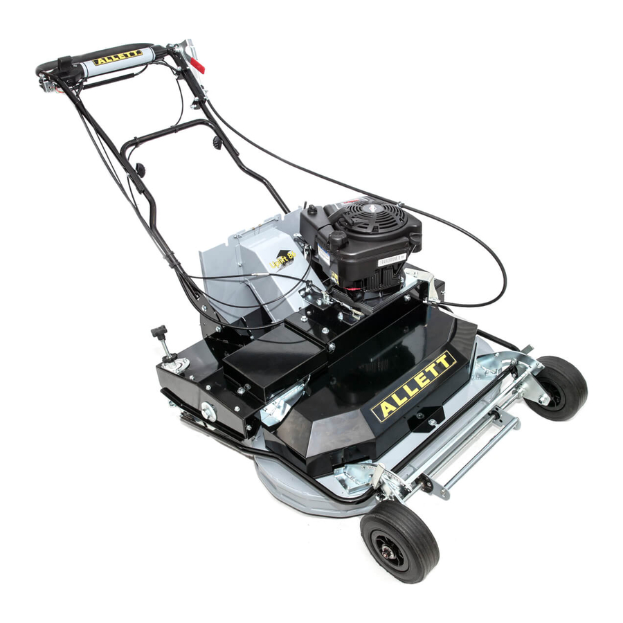
UPLIFT86
Rotary Mower 86cm
(F016J11578 Issue A – Nov 2018)
English version – Original instructions
Allett Ltd
Tel: +44 (0) 1889 271503
Fax: +44 (0) 1889 271321
For Allett spare parts
Tel: +44 (0) 1889 272095
Fax: +44 (0) 1889 271321
Sales@allett.co.uk
www.allett.co.uk
Advertisement
Table of Contents

Related Manuals for Allett UPLIFT86


Summary of Contents for Allett UPLIFT86
- Page 1 English version – Original instructions Allett Ltd Regal House, Airfield Industrial Estate, Hixon, Stafford, ST18 0PF, United Kingdom Tel: +44 (0) 1889 271503 Fax: +44 (0) 1889 271321 For Allett spare parts Tel: +44 (0) 1889 272095 Fax: +44 (0) 1889 271321 Sales@allett.co.uk www.allett.co.uk...
- Page 2 READ THIS MANUAL BEFORE USING AN ALLETT UPLIFT86 ROTARY MOWER. YOUR SAFETY IS INVOLVED IT IS ESSENTIAL THAT OPERATORS STUDY THIS DOCUMENT FOR THEIR OWN SAFETY.
-
Page 3: Table Of Contents
Contents 1.0 Introduction 1.1 Model type and serial number 2.0 Pictograms and Decals 3.0 Safety notes 4.0 Assembly 4.1 Fitting the right and left hand wheel assemblies 4.2 Unfolding the upper handle bar 4.3 Unfolding the lower handle bar 4.4 Attaching the cable clips 4.5 Fitting the grass bag 5.0 Operating controls 6.0 Using your mower... -
Page 4: Introduction
The safety precautions outlined in this manual and all other generally recognised regulations on safety must be observed at all times. Any modifications carried out to a Uplift86 mower will relieve Allett Ltd of liability for any resulting damage or injury. -
Page 5: Pictograms And Decals
Pictograms and Decals Fast engine speed Refer to operator’s manual for information Engine STOP position Slow engine speed • WARNING: Sharp blades • Do not touch rotating blades. The blades continue to rotate after the mower is switched off • Refer to manual before carrying out maintenance •... -
Page 6: Safety Notes
3.0 Safety notes Read these instructions carefully, be familiar with the controls and the proper use of the lawnmower. Learn how to stop the lawnmower quickly in an emergency. Never allow children or people unfamiliar with these instructions to use the lawnmower. -
Page 7: Assembly
Start the engine carefully according to instructions and with feet well away from the blades. Do not tilt the mower when starting. Keep clear of the discharge opening at all times. Never pick up or carry a lawnmower while the engine is running. Do not put hands or feet near or under rotating parts while the lawnmower is being operated. -
Page 8: Unfolding The Upper Handle Bar
4.2 Unfolding the upper handle bar 1) Unfold and align holes in both handle bars 2) Pass the tie bar through the holes and secure with the plastic wing nut 3) Tighten both wing nuts each side by hand 4.3 Unfold the lower handle bar 1) Use 2 x 13mm spanners to undo both the lower M8 Nyloc nuts 2) Move the lower handle bar into a comfortable position for the operator... -
Page 9: Fitting The Grass Bag
4.5 Fitting the grass bag 1) Lift the flap and pass it through the grass bag handle 2) Fit the grass bag by lowering the frame into the slots on the mower DO NOT operate with out the grass bag fitted or the optional “cut and drop shoot”... -
Page 10: Operating Controls
5.0 Operating controls 1) Throttle & engine stop lever 11) Cable adjuster - Blade brake clutch 2) Safety/Operator presence lever 12) Height of cut indicator & clamp 3) Blade engagement lever 13) Scraper/prop 4) Land roll engagement lever 14) Gear lever 15) Cable adjuster –... -
Page 11: Using Your Mower
Check the oil level and fill with petrol before starting – See maintenance section The Briggs and Stratton engine fitted to the Uplift86 has a ReadyStart ® System. This features a temperature controlled automatic choke. It does not have a manual choke or primer. -
Page 12: Stopping The Engine
6.2 Stopping the engine To stop the engine, proceed as follows: Disengage the red blade engagement lever to stop the blades Release the land drive lever to stop the forward travel Move the throttle lever to the furthest back position, this will STOP the engine Engage the Park brake by pulling the lever and latching it in place... -
Page 13: Height Of Cut Adjustment
6.3 Height of cut adjustment The Uplift86 uses 2 micro height adjusters to move the front wheels and rear roller simultaneously. This gives infinite control of the cut height. Loosen the lower adjuster lock on both sides Release Front adjuster clamp locks on both sides Turn the hand wheels: Clockwise to cut higher... -
Page 14: Engaging Drive To The Cutting Blades
Tips: When collecting debris for the optimum performance set the height of cut just above the grass height. For best results adjust the height of cut on a flat level surface. Because of the high vacuum effect created by the blades it may be necessary to set the height of cut to be greater than normal then gradually reduce to meet the desired cut height. -
Page 15: Park Brake
Clean the exterior of the machine thoroughly using a soft brush and cloth. Remove all debris, especially from the air filter and engine fins. If the mower should happen to fail despite the care taken in manufacture and testing, repair should be carried out by an authorised Allett dealer. -
Page 16: Adjusting Land Drive Cable
7.1 Adjusting land drive clutch cable If the mower does not drive adequately when the clutch drive lever is held against the handle bars it may be necessary to adjust the land drive cable. Proceed as follows: Tools required: 10mm spanner x 2 Using a spanner loosen the lock nuts Move the adjuster OUT in the direction shown. - Page 17 With the blade engagement lever pulled back, make sure the centre of the screw head is aligned with the ‘run’ mark as shown below: 23kg (50Lbs) pull from spring ‘run’ mark Release the blade engagement lever, make sure the centre of the screw head is in the brake zone as shown below: Brake Brake...
-
Page 18: Checking The Engine Oil
If the blades turn before the clutch drive lever is operated, move the adjuster UP towards the handle bar. Making sure the screw head is with ✓ in the ‘brake zone’ This mower is fitted with a blade brake clutch. When the blade clutch lever is disengaged the brake device ensures that the blades rapidly come to a stop. -
Page 19: General Engine Maintenance
7.8 Checking blade condition The cutting performance of the Uplift86 is highly dependent on the condition of the blades. Poorly maintained parts will lead to a poor quality of cut. Cutting regularly in sandy conditions will accelerate blade wear, so blade condition should be checked more frequently. -
Page 20: Blade Removal
Make the mower SAFE then tilt the mower back then use the prop/scraper to secure the deck in a tilted position. Make sure the prop is placed securely under the front of deck. A new blade has an approximate 10 degree twist at each end and a bevel of 30 degrees for the cutting edge. -
Page 21: Blade Sharpening
Tools required: 19mm A/F socket and 90Nm Torque wrench Clean the blade mounting surfaces. Fit the blade over the central boss and the two cap head screws. Fit the blades with the fins facing up. The blades have a LEFT and RIGHT hand version as shown. -
Page 22: Tensioning The Blade Brake Clutch Belt
7.12 Tensioning the Blade brake clutch belt Make the mower SAFE then proceed as follows: Tools required: 13mm A/F spanner 35mm A/F spanner (1-3/8” ) 6mm Allen key Using a spanner loosen the 3 deck guard fasteners and remove the guard Using an Allen key loosen the cap head bolt on the adjuster Using the 35mm spanner turn the... -
Page 23: Tensioning The Spindle Timing Belt
7.13 Tensioning the Spindle timing belt Make the mower SAFE then proceed as follows: Tools required: 13mm A/F socket and ratchet 13mm spanner Using a spanner loosen the 3 deck guard fasteners and remove the guard Using a socket and ratchet loosen the 4 fasteners securing the idler bracket to the deck and a spanner to loosen the adjuster screw lock nut... -
Page 24: Timing The Blades
7.15 Adjusting the final drive chain tension The Uplift86 is fitted with a spring operated chain tensioner. This will ensure the chain tension will be constantly maintained. Every 2 weeks check the chain tension and make sure the adjuster is free to move. -
Page 25: Adjusting The Rear Roller Scraper
7.16 Adjusting the rear roller scraper Make the mower SAFE then proceed as follows: Tools required: 10mm spanner x2 Using a pair of spanners loosen the rear roller scraper fasteners. Then move the scraper nearer or further from the roller. Should the scraper not be required position it in the furthest position from the roller - do not remove it, it adds strength to the roller assembly... -
Page 26: Park Brake Adjustment
7.18 Park brake adjustment To set the park brake so that the Tools required: 13mm spanner Set the Park brake lever in an appropriate slot Locate the adjuster nut on the transmission If the Park brake lever locates in a slot but is too loose - adjust the nut clockwise to move ... -
Page 27: Maintenance Schedule
7.21 Maintenance schedule Activity Task Daily Weekly Monthly Yearly Check ● Engine oil level ● Fuel level ● Air cleaner condition ● Guards in place ● Cutting blades ● Fasteners ● Chain and belt tension ● Spark plug ● Tire pressures Clean ●... -
Page 28: Vibration Reduction
Best practices for reducing noise emission: Forcing the mower to cut longer grass than intended or setting it to work at great depths may cause higher levels of noise emission. Fitting non-standard Allett blades may increase noise emission too. Damaged exhausts or loose guards can increase noise emissions. Therefore, before use inspect the exhaust system for signs of wear and ensure the guards are securely attached and in good condition. -
Page 29: Ec Declaration Of Conformity
5.9m/s/s Uncertainty K: 1.5m/s/s Notified body: AVT Reliability, Warrington Cheshire Technical construction file is kept by: Allett Ltd, Regal House, Airfield Industrial Estate, Hixon, Staffordshire, ST18 0PF, UK I hereby declare that the equipment named above has been tested and found to comply with the relevant sections of the above referenced specifications. -
Page 30: Fault Finding When Mowing
11.0 Fault finding when mowing Problem Possible cause Remedy Occasional blades of uncut Forward speed too fast Reduce forward travel speed. or damaged grass Height of cut too high Reduce height of cut Blunt blade Grind/recondition blade Drive belt/clutch slipping Adjust belt tension/clutch cable Engine speed too low Adjust engine speed to maximum... -
Page 31: Specification
12.0 Specification Model name UPLIFT86 864mm (34”) Cutting width Engine Briggs and Stratton 950E Engine fuel/oil capacity 1.1L Unleaded fuel, 0.6L oil SAE 10W-30 Power output (Net) 12.88Nm @3060rpm (Calculated to be 5.5hp @3060rpm) Transmission 5 speed manual gearbox giving forward speeds of 1.2 –... -
Page 32: Guarantee
Always insist on genuine Allett spares or parts. Any damage caused to the product through the fitting of parts not made or approved by Allett is not covered by the guarantee. Your statutory rights are not affected by this guarantee. -
Page 33: Parts Section
14.0 Parts section UPLIFT86... - Page 34 UPLIFT86 – Parts Section TOP HANDLE ASSEMBLY REAR ROLLER DRIVE FRONT WHEEL GRASS ASSEMBLY COLLECTION MAINFRAME ASSY SPINDLE/BLADE DRIVE ASSEMBLY REAR FRONT BRUSH ROLLER (OPTIONAL EXTRAS) ASSEMBLY...
- Page 35 MODEL UPLIFT86: - Mainframe Assembly (Fig 1)
- Page 36 M8x30 BUTTON HEAD SKT SET SCREW M830BHSS GEARBOX DECAL F016J10628 BELT COVER GEAR LEVER F016J10609 BELT COVER F016J10529 DECAL ALLETT MEDIUM AM81621 L.H. PIVOT BUSH F016A57676 REAR ROLLER SCRAPER F016J10439 REAR ROLLER ARM LH FAB F016J10525 REAR ROLLER ARM Rh FAB...
- Page 37 M5 NYLOC NUT F016L59926 HINGE SHAFT F016J10572 COLLECTION PLATE F016J11568 CHUTE COVER F016J11569 LOWER HANDLE WELDED ASSEM F016J11571 ROTARY MOWER SAFETY DECAL F016J10624 SKIRT FAB F016J10520 SKIRT SIDE PRESSING RH F016J10518 SKIRT SIDE PRESSING LH F016J10519 ENGINE PRESSED PILLAR F016J11462 CLUTCH REACTION BRACKET F016J11473 ENGINE TRAY...
- Page 38 MODEL UPLIFT86:- Roller Drive Assembly (Fig 2)
- Page 39 MODEL UPLIFT86:- Roller Drive Assembly (Fig 2) ITEM NO. PART NUMBER DESCRIPTION USED WM10C WASHER M10 FORM C F016J11489 TENSIONER SLEEVE BOSS M6x50 BOLT M6 x 50 BSG1038 CHAIN TENSIONER SLEEVE SHORT NNM10 M10 NYLOC NUT AM81197 EXTERNAL CIRCLIP 19mm DIA...
- Page 40 F016J10545 TRANSMISSION PULLEY WELDED ASSEM F016J10980 DOUBLE IDLER FAB F016J10984 DOUBLE IDLER PIVOT BOSS NNM8 NUT M8 NYLOC SM835 SET SCREW M8 x 35 WM8G PLAIN WASHER M8 FORM G F016J11011 FLANGED IDLER PULLEY N11002 NUT 3/8" NYLOC B11020 BOLT 3/8 x 2 1/4" F016J11504 SLOTTED CLUTCH SPACER BELT GUIDE...
- Page 41 MODEL UPLIFT86:- Spindle/Blade Drive Assembly (Fig 3) MODEL UPLIFT86:- Spindle/Blade Drive Assembly (Fig 3) ITEM NO. DESCRIPTION PART NUMBER USED M5x6 SOCKET HD MACHINED F016J10670 2 & 10 HARDENED WASHER M12 W2-M12 FLAT WASHER M12 WM12 SET SCREW M12 x 25...
- Page 42 NUT M8 NYLOC NNM8 M8 NUT PLAIN SET SCREW M12X65 SM1265 SET SCREW M8X100 SM8100 SPRING WASHER SWM8 SET SCREW M8 x 16 SM816 M8 PLAIN WASHER SET SCREW M8x40 SM840 KEY 6 X 6 X 44 FORM C AM81283 6 x 6 x 25 KEY AM81465 SET SCREW M8X75...
- Page 43 MODEL UPLIFT86:- Rear Roller Assembly (Fig 4)
- Page 44 MODEL UPLIFT86:- Rear Roller Assembly (Fig 4) ITEM NO. DESCRIPTION PART NUMBER USED HD OUTER ROLLER WELD ASSY F016J11440 CENTRE DRUM ASSEMBLY F016J11445 HD R/ROLLER SHAFT F016J11411 HD R/ROLLER BEARING HOUSING F016J11417 15mm BEARING F016J11418 19T Sprocket F016J10453 REAR ROLLER LOCKING COLLAR...
- Page 45 MODEL UPLIFT86:- Top Handle Assembly (Fig 5) MODEL UPLIFT86:- Top Handle Assembly (Fig 5) ITEM NO. DESCRIPTION PART NUMBER USED TANK SUPPORT BAR F016A75286 WING NUT F016L66135 SET SCREW M6 x 20 SM620 TOP HANDLE LOOP F016J11572 THROTTLE HANDLE PLATE...
- Page 46 F016J10558 SCREW M5 x 32 POZI PAN f016A75751 O-Ring (20mm Id X 3mm Sect.) F016A75826 READ MANUAL & ENGINE STOP DECAL F016J10626 ALLETT SMALL 201x30 DECAL CURVED AM81639 M5 NYLOC NUT F016L59926 M2 SCREW F016J10667 BLADE CLUTCH BACK PLATE FAB...
- Page 47 MODEL UPLIFT86:- Front Wheel Assembly (Fig 6) MODEL UPLIFT86:- Front Wheel Assembly (Fig 6) ITEM NO. DESCRIPTION PART NUMBER USED FRONT WHEEL SHAFT F016J10608 3/4" STARLOCK WASHER F016J10287 WASHER 20mm F016A58577 NUT M12 NYLOC NNM12 M12 WASHER FORM A M12 WASHER...
- Page 48 MODEL UPLIFT86:- Grass Collector Assembly (Fig 7) MODEL UPLIFT86:- Grass Collector Assembly (Fig 7) ITEM NO. DESCRIPTION PART NUMBER USED GRASS COLLECTION FRAME F016J10472 GRASS COLLECTION BAG F016J10471...
- Page 49 MODEL UPLIFT86:- Brush Assembly (Optional) (Fig 8) Brush Assembly Options DESCRIPTION PART NUMBER SOFT BRUSH + CARRIER F016J11580 MEDIUM STIFFNESS BRUSH + CARRIER F016J11585 HARD STIFFNESS BRUSH + CARRIER F016J11590 MODEL UPLIFT86:- Brush Assembly (Fig 8) ITEM NO. DESCRIPTION PART NUMBER...
-
Page 50: Wiring Schematic
SET SCREW M6 x 30 SM630 15.0 Wiring schematic OPC = Operator presence control Black Green Notes...
Need help?
Do you have a question about the UPLIFT86 and is the answer not in the manual?
Questions and answers