Table of Contents
Advertisement
Advertisement
Table of Contents

Related Manuals for JST AP-K2


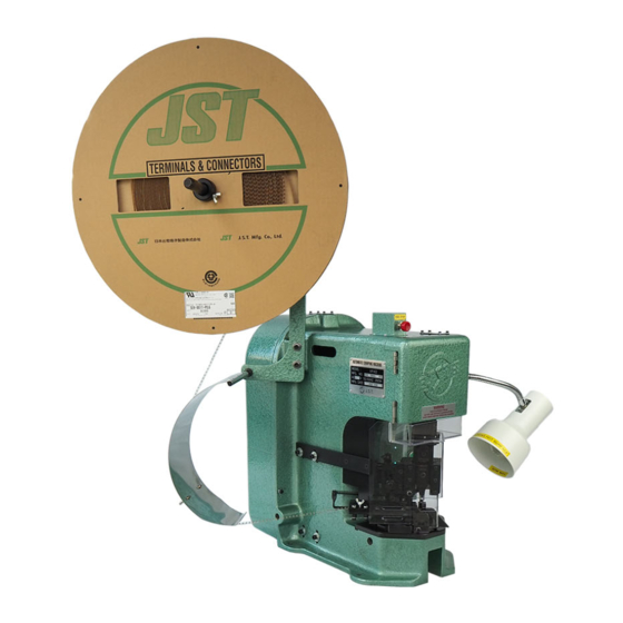
Summary of Contents for JST AP-K2
- Page 1 AP-K2 CRIMPING MACHINE OPERATION MANUAL...
- Page 2 The AP-K2 semi-automatic crimping machine is easy to operate, and is suitable for mass production of crimped harnesses with chain terminals. Before using the AP-K2 please read this manual to ensure that you are familiar with the features of the machine and the layout of the operating controls.
-
Page 3: Table Of Contents
Page 25 Exploded views and parts list AP-K2 Crimping machine exploded view Page 26 MK-L Applicator Page 28 MKS-L Applicator Page 30 MKF-L Applicator Page 32 MKS-LS Applicator Page 34 H:\0 - Quality Documents\2 Department\Tech Serv\Application tooling\Presses\AP-K2\TS009-02 AP-K2 Operation Manual.doc... -
Page 4: Specifications
º Weight 6.8 Kg º Weight 4.5 Kg º Feed pitch 30mm max. º Feed pitch 30mm max. º Crimp height adjustment: Dial type º Crimp height adjustment: Dial type H:\0 - Quality Documents\2 Department\Tech Serv\Application tooling\Presses\AP-K2\TS009-02 AP-K2 Operation Manual.doc... -
Page 5: Installing The Machine
CAUTION Ensure that the belt cover of the crimping machine does not overhang the edge of the mounting surface. H:\0 - Quality Documents\2 Department\Tech Serv\Application tooling\Presses\AP-K2\TS009-02 AP-K2 Operation Manual.doc... -
Page 6: Machine Preparation
Ensure that the shank is correctly located in the correctly. ram. There is a danger of major tooling damage if the tooling is not located correctly (as in the photograph below). H:\0 - Quality Documents\2 Department\Tech Serv\Application tooling\Presses\AP-K2\TS009-02 AP-K2 Operation Manual.doc... -
Page 7: Prevention Of Tooling Damage
Picture 3, is a zoomed in view of the punch and anvil when the rubber collar is left off. The two circled points are the points of contact where the damage will be caused. Picture 3. H:\0 - Quality Documents\2 Department\Tech Serv\Application tooling\Presses\AP-K2\TS009-02 AP-K2 Operation Manual.doc... -
Page 8: Prevention Of Terminal Damage
INCORRECT. CORRECT. H:\0 - Quality Documents\2 Department\Tech Serv\Application tooling\Presses\AP-K2\TS009-02 AP-K2 Operation Manual.doc... -
Page 9: Mounting The Terminal Reel
Feed the terminal strip between terminal is centralised over the anvil. Rotate the the guide rails. wing bolt counter- clockwise to lower the pressure plate so that pressure is applied to the terminal. H:\0 - Quality Documents\2 Department\Tech Serv\Application tooling\Presses\AP-K2\TS009-02 AP-K2 Operation Manual.doc... -
Page 10: Setting The Counter
3-5. Mounting the safety guard There are many types of safety guards available, please consult JST for details. A RELEVANT SET OF SAFETY GUARDS IS ALWAYS DESPATCHED WITH THE MACHINE H:\0 - Quality Documents\2 Department\Tech Serv\Application tooling\Presses\AP-K2\TS009-02 AP-K2 Operation Manual.doc... -
Page 11: Operation
If the press is left partway through a cycle it will try to complete the cycle when the motor is turned on and this action could result in damage being caused to the tooling. H:\0 - Quality Documents\2 Department\Tech Serv\Application tooling\Presses\AP-K2\TS009-02 AP-K2 Operation Manual.doc... -
Page 12: Inspection Before Operation
If any problems occur during operations, immediately press the Power Off push-button and investigate the reason If the problem requires the removal of safety guards, contact a person authorised to remove the guards. ON NO ACCOUNT REMOVE SAFETY GUARDS IF YOU ARE NOT AUTHORISED TO DO SO. H:\0 - Quality Documents\2 Department\Tech Serv\Application tooling\Presses\AP-K2\TS009-02 AP-K2 Operation Manual.doc... -
Page 13: Applicator
When a satisfactory result is achieved, replace the guards, connect the crimping machine to the power supply and recommence the crimping operation. H:\0 - Quality Documents\2 Department\Tech Serv\Application tooling\Presses\AP-K2\TS009-02 AP-K2 Operation Manual.doc... -
Page 14: Bell Mouth Adjustment
Department detailing the points to inspect on a crimped terminal to achieve results as per our specifications. A copy is issued with every AP-K2N Crimping machine supplied to a customer but please contact JST if you require further copies. Adjustment screw... -
Page 15: Feed-Finger Travel Adjustment
The lower dial, marked with numbers 1 - 8, is for the insulation crimp height. JST do not advise pad settings for wire sizes, as is the practice of some manufacturers. We believe that the best method to adopt is to specify crimp-heights and adjust the dials until the desired crimp-height is achieved. -
Page 16: Die Part Replacement
Apply grease to the surface of the cam-roller. APPLY GREASE HERE Apply grease to the four faces of the applicator ram. CAUTION Apply grease sparingly because excess grease attracts dirt and scrap insulation etc. H:\0 - Quality Documents\2 Department\Tech Serv\Application tooling\Presses\AP-K2\TS009-02 AP-K2 Operation Manual.doc... -
Page 17: Maintenance
CAUTION ENSURE THAT FINGERS BECOME TRAPPED BETWEEN THE V-BELT AND THE FLY-WHEEL Step 2 With the aid of a pair of internal circlip pliers, remove the circlip retaining the fly-wheel. H:\0 - Quality Documents\2 Department\Tech Serv\Application tooling\Presses\AP-K2\TS009-02 AP-K2 Operation Manual.doc... - Page 18 PHOTO A photo A. If the clutch is assembled as in photo B, it will not be possible to re-mount the flywheel onto the shaft. PHOTO B H:\0 - Quality Documents\2 Department\Tech Serv\Application tooling\Presses\AP-K2\TS009-02 AP-K2 Operation Manual.doc...
-
Page 19: Inspection And Repair
Next, check that the ram does not wobble and that it moves smoothly. Step 4 Make a final check that the ram is stable and the screws are secure. Replace cap head screws in ram cover. H:\0 - Quality Documents\2 Department\Tech Serv\Application tooling\Presses\AP-K2\TS009-02 AP-K2 Operation Manual.doc... -
Page 20: Positioning The Solenoid Bracket
Tighten the cap head screws on the retaining bracket, close the belt cover and replace the socket screws in the bracket. Clearance 10 - 11mm H:\0 - Quality Documents\2 Department\Tech Serv\Application tooling\Presses\AP-K2\TS009-02 AP-K2 Operation Manual.doc... -
Page 21: Fault Finding
5. The Ram moves incorrectly, or the too slowly, or wrong grease is stops at Bottom applied to the roller Dead Centre clutch 3. The applicator is seized H:\0 - Quality Documents\2 Department\Tech Serv\Application tooling\Presses\AP-K2\TS009-02 AP-K2 Operation Manual.doc... - Page 22 Close the belt cover and re-secure the catch with the cap head socket screws. 2. The Ram does not move (1) The Connecting Pin is broken Replace the connecting pin with a new one H:\0 - Quality Documents\2 Department\Tech Serv\Application tooling\Presses\AP-K2\TS009-02 AP-K2 Operation Manual.doc...
- Page 23 The Ram ‘clunks’ several times A Spring has become slack Replace the spring with a new one. The Clutch Lever or Stopper is worn out Replace parts with new ones. H:\0 - Quality Documents\2 Department\Tech Serv\Application tooling\Presses\AP-K2\TS009-02 AP-K2 Operation Manual.doc...
- Page 24 See section 7 for details of grease specification. The Applicator is seized Contact Technical Services Department for assistance. Part of the Clutch assembly is missing Check that all the Stick Rollers are assembled. H:\0 - Quality Documents\2 Department\Tech Serv\Application tooling\Presses\AP-K2\TS009-02 AP-K2 Operation Manual.doc...
-
Page 25: Electrical Circuit Diagram
Suggestion 3: If any trouble occurs, turn off the motor switch quickly and check the machine. When examination of moving parts of the machine is required, the plug must be pulled out from the electric outlet for safety. Electric circuit diagram. H:\0 - Quality Documents\2 Department\Tech Serv\Application tooling\Presses\AP-K2\TS009-02 AP-K2 Operation Manual.doc... -
Page 26: Exploded Views And Parts List
SECTION 8.EXPLODED VIEWS AND PARTS LISTS H:\0 - Quality Documents\2 Department\Tech Serv\Application tooling\Presses\AP-K2\TS009-02 AP-K2 Operation Manual.doc... - Page 27 Ret. Ring (C-40) K2-B128 Lead & plug for footswitch K2-0315 173b Spring post K2-4179 Mains power lead K2-B317A Spring K2-4155 Hinge (without spring) K2-B167B Spring post K2-4177 Stop/Reset switch K2-EOA H:\0 - Quality Documents\2 Department\Tech Serv\Application tooling\Presses\AP-K2\TS009-02 AP-K2 Operation Manual.doc...
- Page 28 H:\0 - Quality Documents\2 Department\Tech Serv\Application tooling\Presses\AP-K2\TS009-02 AP-K2 Operation Manual.doc...
- Page 29 Shear blade anvil (B) Feed finger pin MA01-347 Crimper anvil (A) Feed finger spring MA01-348 Crimper anvil (B) Feed finger Shear blade Returning spring MA01-349 Spacer Note: : mm dia. H:\0 - Quality Documents\2 Department\Tech Serv\Application tooling\Presses\AP-K2\TS009-02 AP-K2 Operation Manual.doc...
- Page 30 H:\0 - Quality Documents\2 Department\Tech Serv\Application tooling\Presses\AP-K2\TS009-02 AP-K2 Operation Manual.doc...
- Page 31 Feed finger spring MA01-348 Spacer Plate (L) MA03-102 Scrap cover Plate (R) MA03-103 Wire block Hex. Nut (M4, type-1) Insulation block Stroke adj. shaft MA01-331 Block ring MA01-225 Note: : mm dia. H:\0 - Quality Documents\2 Department\Tech Serv\Application tooling\Presses\AP-K2\TS009-02 AP-K2 Operation Manual.doc...
- Page 32 H:\0 - Quality Documents\2 Department\Tech Serv\Application tooling\Presses\AP-K2\TS009-02 AP-K2 Operation Manual.doc...
- Page 33 Stroke adj. Bearing MA01-332 Crimper anvil (A) Hook NF-4113 Crimper anvil (B) Hex. Nut MA01-333 Finger holder Note : : mm dia. Note: * will vary (A,B,…..) depending on the terminal H:\0 - Quality Documents\2 Department\Tech Serv\Application tooling\Presses\AP-K2\TS009-02 AP-K2 Operation Manual.doc...
- Page 34 H:\0 - Quality Documents\2 Department\Tech Serv\Application tooling\Presses\AP-K2\TS009-02 AP-K2 Operation Manual.doc...
- Page 35 Hex. Socket head bolt (M3x6) Hex. Socket head bolt (M5x50) Rivet (1.5x5) Hex. Nut (M6, type-1) Spring washer (6) Compressed coil spring LS-B343 Tension spring LS-B344 Ball plunger LS-B345 Hex. Socket head screw (M4x10) H:\0 - Quality Documents\2 Department\Tech Serv\Application tooling\Presses\AP-K2\TS009-02 AP-K2 Operation Manual.doc...
- Page 36 For full up to date address details go to: www.jst-mfg.com/e00com/e31com.html In line with a policy of continual development JST reserves the right to change the specifications of the goods described in this manual at any time and without prior notice.
Need help?
Do you have a question about the AP-K2 and is the answer not in the manual?
Questions and answers