Table of Contents

Related Manuals for JST AP-K2N


Summary of Contents for JST AP-K2N
- Page 1 AP-K2N CRIMPING MACHINE OPERATION MANUAL H:\0 - Quality Documents\2 Department\Tech Serv\Application tooling\Presses\AP-K2N\TS010-00 AP-K2N Operation Manual.doc This datasheet has been downloaded from http://www.digchip.com at this page...
- Page 2 The AP-K2N semi-automatic crimping machine is easy to operate, and is suitable for mass production of crimped harnesses with chain terminals. Before using the AP-K2N please read this manual to ensure that you are familiar with the features of the machine and the layout of the operating controls.
-
Page 3: Table Of Contents
7 - 1 Lubrication......................19 7 - 2 Inspection and Repair..................21 8. FAULT FINDING....................22 9. EXPLODED VIEWS AND PARTS LISTS............26 AP-K2N Crimping Machine Exploded Diagram..………........26 MK-L Applicator................………....28 MKS-L Applicator……………............……….....30 MKF-L Applicator................……….....32 MKS-LS Applicator.................………..34 H:\0 - Quality Documents\2 Department\Tech Serv\Application tooling\Presses\AP-K2N\TS010-00 AP-K2N Operation Manual.doc... -
Page 4: Specifications
º Weight 6.8 Kg º Weight 4.5 Kg º Feed pitch 30mm max. º Feed pitch 30mm max. º Crimp height adjustment: Dial type º Crimp height adjustment: Dial type H:\0 - Quality Documents\2 Department\Tech Serv\Application tooling\Presses\AP-K2N\TS010-00 AP-K2N Operation Manual.doc... -
Page 5: Installing And Transporting The Machine
(as shown in the photograph on the left). The machine should always be transported by placing the lifting handles onto the arms of a fork-lift truck. DO NOT ATTEMPT TO LIFT MANUALLY. H:\0 - Quality Documents\2 Department\Tech Serv\Application tooling\Presses\AP-K2N\TS010-00 AP-K2N Operation Manual.doc... -
Page 6: Preparation For Operation
Securely fasten the clamps with the 5 mm hexagon key, Remove the protective rubber collar from under the dials and visually check that the tooling is mounted correctly. on the applicator ram. H:\0 - Quality Documents\2 Department\Tech Serv\Application tooling\Presses\AP-K2N\TS010-00 AP-K2N Operation Manual.doc... -
Page 7: Mounting The Terminal Reel
Step 2 Place the first terminal at the correct crimping position. Release the hook from the feed plate to allow the pressure pad to apply pressure on the strip. H:\0 - Quality Documents\2 Department\Tech Serv\Application tooling\Presses\AP-K2N\TS010-00 AP-K2N Operation Manual.doc... -
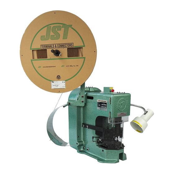
Page 8: Mounting The Safety Guard
Illustration of Terminal reels mounted on the AP-K2N Crimping Machine MK-L MKS-L 3.4 Mounting the safety guard Step 3 Select the appropriate side guard (JST UK-4), and mount For reasons of safety and to comply with legislation, onto the side guard support bracket (JST UK-9), using safety guards must always be mounted to the crimping the countersunk screws supplied. - Page 9 Step 3 Select the appropriate side guard (JST UK-3), and mount onto the side guard support bracket (JST UK-9), using the countersunk screws provided. H:\0 - Quality Documents\2 Department\Tech Serv\Application tooling\Presses\AP-K2N\TS010-00 AP-K2N Operation Manual.doc...
- Page 10 Tighten the screws and check that the guards are Select the appropriate side guard (JST UK-3), and mount correctly and securely fitted. onto the side guard support bracket (JST UK-9), using the countersunk screws supplied.. H:\0 - Quality Documents\2 Department\Tech Serv\Application tooling\Presses\AP-K2N\TS010-00 AP-K2N Operation Manual.doc...
- Page 11 Please contact the JST Technical Department for replacement guards. Step 3 Remove the two upper motor fixing screws and clamp the side guard support bracket onto the press utilizing these screws. H:\0 - Quality Documents\2 Department\Tech Serv\Application tooling\Presses\AP-K2N\TS010-00 AP-K2N Operation Manual.doc...
-
Page 12: Control Box Configuration
Wait for at least one minute, press the Circuit Protector Push-button in, then press the Power On push-button. Contact the JST Service Department if you think that the Circuit Protector is activated too often because the press may require attention. -
Page 13: Operation
If the press is left part-way through a cycle it will try to complete the cycle when the motor is turned on and this action could result in damage being caused to the tooling. H:\0 - Quality Documents\2 Department\Tech Serv\Application tooling\Presses\AP-K2N\TS010-00 AP-K2N Operation Manual.doc... -
Page 14: Operation Under Power
If the problem requires the removal of safety guards, contact a person authorised to remove the guards. ON NO ACCOUNT REMOVE SAFETY GUARDS IF YOU ARE NOT AUTHORISED TO DO SO. H:\0 - Quality Documents\2 Department\Tech Serv\Application tooling\Presses\AP-K2N\TS010-00 AP-K2N Operation Manual.doc... -
Page 15: Applicator
When a satisfactory result is achieved, replace the guards, connect the crimping machine to the power supply and recommence the crimping operation. H:\0 - Quality Documents\2 Department\Tech Serv\Application tooling\Presses\AP-K2N\TS010-00 AP-K2N Operation Manual.doc... -
Page 16: Bell Mouth Adjustment
Technical Department detailing the points to inspect on a crimped terminal to achieve results as per our specifications. A copy is issued with every AP-K2N Crimping machine supplied to a customer but please contact JST if you require further copies. -
Page 17: Feed-Finger Travel Adjustment
The lower dial, marked with numbers 1 - 8, is for the insulation crimp height. JST do not advise pad settings for wire sizes, as is the practice of some manufacturers. We believe that the best method to adopt is to specify crimp-heights and adjust the dials until the desired crimp- height is achieved. -
Page 18: Die Part Replacement
If you consider that the replacement process is too difficult, or the tooling has sustained damage, please contact JST to either send back the tooling for repair or alternatively a JST Service Engineer can visit your company to repair the tool on site. -
Page 19: Crimping Machine Maintenance
ENSURE THAT FINGERS DO NOT BECOME TRAPPED BETWEEN THE V-BELT AND THE FLY-WHEEL Step 2 With the aid of a pair of internal circlip pliers, remove the circlip retaining the fly-wheel. H:\0 - Quality Documents\2 Department\Tech Serv\Application tooling\Presses\AP-K2N\TS010-00 AP-K2N Operation Manual.doc... - Page 20 A. PHOTO A If the clutch is assembled as in photo B, it will not be possible to re-mount the flywheel onto the shaft. PHOTO B H:\0 - Quality Documents\2 Department\Tech Serv\Application tooling\Presses\AP-K2N\TS010-00 AP-K2N Operation Manual.doc...
-
Page 21: Inspection And Repair
Next, check that the ram does not wobble and that it moves smoothly. Make a final check check that the ram is stable and the screws are secure. Replace cap head screws in ram cover. H:\0 - Quality Documents\2 Department\Tech Serv\Application tooling\Presses\AP-K2N\TS010-00 AP-K2N Operation Manual.doc... -
Page 22: Fault Finding
→ → → → → → → → stops at Bottom applied to the roller Dead Centre clutch 3. The applicator is seized H:\0 - Quality Documents\2 Department\Tech Serv\Application tooling\Presses\AP-K2N\TS010-00 AP-K2N Operation Manual.doc... - Page 23 2. The Ram does not move (1) The Connecting Pin is broken Replace the connecting pin with a new one. Connecting pin AP-K2N CRIMPING MACHINE H:\0 - Quality Documents\2 Department\Tech Serv\Application tooling\Presses\AP-K2N\TS010-00 AP-K2N Operation Manual.doc...
- Page 24 3. The Ram ‘clunks’ several times (1) A Spring has become slack Replace the spring with a new one. (2) The Clutch Lever or Stopper is worn out Replace parts with new ones. H:\0 - Quality Documents\2 Department\Tech Serv\Application tooling\Presses\AP-K2N\TS010-00 AP-K2N Operation Manual.doc...
- Page 25 (3) The Applicator is seized Contact the JST Technical Services Department for assistance. (4) Part of the Clutch assembly is missing Check that all the Stick Rollers are assembled. H:\0 - Quality Documents\2 Department\Tech Serv\Application tooling\Presses\AP-K2N\TS010-00 AP-K2N Operation Manual.doc...
-
Page 26: Exploded Views And Parts Lists
9. EXPLODED VIEWS AND PARTS LISTS AP-K2N Crimping Machine H:\0 - Quality Documents\2 Department\Tech Serv\Application tooling\Presses\AP-K2N\TS010-00 AP-K2N Operation Manual.doc... - Page 27 H:\0 - Quality Documents\2 Department\Tech Serv\Application tooling\Presses\AP-K2N\TS010-00 AP-K2N Operation Manual.doc...
-
Page 28: Mk-L Applicator
H:\0 - Quality Documents\2 Department\Tech Serv\Application tooling\Presses\AP-K2N\TS010-00 AP-K2N Operation Manual.doc... - Page 29 Feed lever (B) Shear blade anvil (B) MA01-345 Feed finger pin MA01-347 Crimper anvil (A) Feed finger spring Crimper anvil (B) MA01-348 Feed finger Shear blade Returning spring Spacer MA01-349 H:\0 - Quality Documents\2 Department\Tech Serv\Application tooling\Presses\AP-K2N\TS010-00 AP-K2N Operation Manual.doc...
-
Page 30: Mks-L Applicator
H:\0 - Quality Documents\2 Department\Tech Serv\Application tooling\Presses\AP-K2N\TS010-00 AP-K2N Operation Manual.doc... - Page 31 Crimper anvil (A) MA01-347 Feed finger spring MA01-348 Spacer Plate (L) Scrap cover MA03-102 Plate (R) MA03-103 Wire block Hex. Nut (M4, type-1) Insulation block Stroke adj. shaft Block ring MA01-331 MA01-225 H:\0 - Quality Documents\2 Department\Tech Serv\Application tooling\Presses\AP-K2N\TS010-00 AP-K2N Operation Manual.doc...
-
Page 32: Mkf-L Applicator
H:\0 - Quality Documents\2 Department\Tech Serv\Application tooling\Presses\AP-K2N\TS010-00 AP-K2N Operation Manual.doc... - Page 33 NF-4139 Hex. Nut (m4,type-1) Crimper (B) Stroke adj. Shaft Die holder ring MA01-331 Stroke adj. Bearing Crimper anvil (A) MA01-332 Hook NF-4113 Crimper anvil (B) Hex. Nut Finger holder MA01-333 H:\0 - Quality Documents\2 Department\Tech Serv\Application tooling\Presses\AP-K2N\TS010-00 AP-K2N Operation Manual.doc...
-
Page 34: Mks-Ls Applicator
H:\0 - Quality Documents\2 Department\Tech Serv\Application tooling\Presses\AP-K2N\TS010-00 AP-K2N Operation Manual.doc... - Page 35 Hex. Socket head bolt (M5x50) Rivet (1.5 x5) Hex. Nut (M6, type-1) Spring washer (6) Compressed coil spring LS-B343 Tension spring LS-B344 Ball plunger LS-B345 Hex. Socket head screw (M4x10) H:\0 - Quality Documents\2 Department\Tech Serv\Application tooling\Presses\AP-K2N\TS010-00 AP-K2N Operation Manual.doc...
- Page 36 Notes: H:\0 - Quality Documents\2 Department\Tech Serv\Application tooling\Presses\AP-K2N\TS010-00 AP-K2N Operation Manual.doc...
- Page 37 For full up to date address details go to: www.jst-mfg.com/e00com/e31com.html In line with a policy of continual development JST reserves the right to change the specifications of the goods described in this manual at any time and without prior notice.
Need help?
Do you have a question about the AP-K2N and is the answer not in the manual?
Questions and answers