Table of Contents
Advertisement
Available languages
Available languages
Quick Links
BEDIENUNGSANWEISUNG
mit Montageanweisungen
INSTRUCTION FOR USE
and installation
D
GB
KE9340.0
Lesen Sie unbedingt die Gebrauchsanleitung
und den Montageplan vor Aufstellung,
Installation sowie Inbetriebnahme.
Please read the users an installation
instructions carefully before installation ot the
appliance and before starting to use.
Service und Kundendienst
Telefon: 0209 - 401 631
Email: kundendienst@kueppersbusch.de
240 249 0000 J81
Advertisement
Chapters
Table of Contents

Related Manuals for Kuppersbusch KE9340.0


Summary of Contents for Kuppersbusch KE9340.0
- Page 1 BEDIENUNGSANWEISUNG mit Montageanweisungen INSTRUCTION FOR USE and installation KE9340.0 Lesen Sie unbedingt die Gebrauchsanleitung und den Montageplan vor Aufstellung, Installation sowie Inbetriebnahme. Please read the users an installation instructions carefully before installation ot the appliance and before starting to use.
-
Page 2: Table Of Contents
Allgemeines Inhalt 1. Allgemeines 1.1 Küppersbusch-Kundendienst 1. Allgemeines Zentrale Kundendienst- / Ersatzteilanforderung 1.1 Küppersbusch-Kundendienst ..........2 Deutschland: 1.2 Garantiebedingungen ............3 Küppersbusch Hausgeräte GmbH 1.3 Hier fi nden Sie..............3 Küppersbuschstraße 16 1.4 Bestimmungsgemäße Verwendung ........3 45883 Gelsenkirchen 2. -
Page 3: Garantiebedingungen
Allgemeines 1.2 Garantiebedingungen 4. In Fällen, in denen die Nachbesserung fehlschlägt oder von uns abgelehnt wird, liefern wir innerhalb der oben Zusätzlich zu seinen Gewährleistungsansprüchen aus genannten Garantiezeit auf Wunsch des Endabneh- seinem Kaufvertrag mit dem Händler leisten wir dem mers kostenfrei gleichwertigen Ersatz. -
Page 4: Sicherheitshinweise Und Warnungen
Sicherheitshinweise und Warnungen 2. Sicherheitshinweise und Warnungen • Sollte sich das Kochfeld durch einen Defekt der Sensorsteuerung nicht mehr abschalten 2.1 Für Anschluss und Funktion lassen, sofort die Haushalts-Sicherung aus- • Die Geräte werden nach den einschlägigen schalten und den Kundendienst rufen. Sicherheitsbestimmungen gebaut. -
Page 5: Für Personen
Sicherheitshinweise und Warnungen 2.3 Für Personen • Diese Geräte können von Kindern ab 8 Jah- ACHTUNG ren sowie von Personen mit reduzierten Anmerkung, die auf eine gefährliche Situa- tion hinweist, deren mögliche Folgen leichte physischen, sensorischen oder mentalen Verletzungen oder Beschädigung des Gerä- Fähigkeiten oder Mangel an Erfahrung und/ tes sind. -
Page 6: Gerätebeschreibung
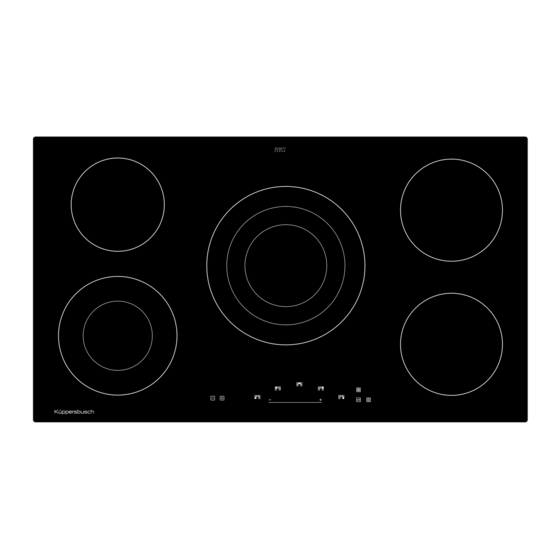
Gerätebeschreibung 3. Gerätebeschreibung Das Dekor kann von den Abbildungen abweichen. 8. Ein/Aus-Taste 1. Kochzone vorne links 9. Kochzonenauswahl-Taste 2. Kochzone hinten links 10. Symbol zur Zuordnung der Lage der Kochzone auf dem Kochfeld 3. Kochzone Mitte 11. Sensorfeld 4. Kochzone hinten rechts 12. -
Page 7: Bedienung Durch Sensortasten
Gerätebeschreibung 3.1 Bedienung durch Sensortasten 3.2 Wissenswertes zum Slider (Sensorfeld) Die Bedienung des Glaskeramik-Kochfeldes erfolgt durch Der Slider funktioniert grundsätzlich wie die Sensortasten, Touch-Control Sensortasten. Die Sensortasten funktio- mit dem Unterschied, dass der Finger auf der Glaskera- nieren wie folgt: mit der Fingerspitze ein Symbol auf der mikoberfl... -
Page 8: Bedienung
Bedienung 4. Bedienung 4.3 Energiespartipps Nachfolgend fi nden Sie einige wichtige Hinweise, um ener- 4.1 Betriebsdauerbegrenzung giesparend und effi zient mit Ihrem neuen Induktionskoch- Das Kochfeld besitzt eine automatische Betriebsdauerbe- feld und dem Kochgeschirr umzugehen. grenzung. • Der Topfbodendurchmesser sollte gleich groß sein wie Die kontinuierliche Nutzungsdauer jeder Kochzone ist der Kochzonendurchmesser. -
Page 9: Tastenbetätigung
Bedienung 4.6 Tastenbetätigung Die hier beschriebene Steuerung erwartet nach der Betä- tigung einer (Auswahl-) Taste anschließend die Betätigung einer nachfolgenden Taste. Die Betätigung der nachfolgenden Taste muss grundsätzlich innerhalb von 10 Sekunden begonnen werden, ansonsten erlischt die Auswahl. 4.7 Kochfeld und Kochzone einschalten 1. -
Page 10: Abschaltautomatik (Timer)
Bedienung 4.11 Abschaltautomatik (Timer) Durch die Abschaltautomatik wird jede eingeschaltete Koch- zone nach einer einstellbaren Zeit automatisch abgeschal- tet. Es können Kochzeiten von 1 bis 99 Minuten eingestellt werden. 1. Kochgeschirr steht auf einer Kochzone und eine Kochstufe (z.B. 3) ist gewählt. Eine Kochzone muss selektiert sein. -
Page 11: Verriegelung
Bedienung 4.12 Verriegelung Durch die Verriegelung kann die Bedienung der Tasten und die Einstellung einer Kochstufe gesperrt werden. Le- diglich die Aus-Taste bleibt zum Ausschalten des Kochfel- des bedienbar. Verriegelung einschalten (während dem Kochen): 1. Kochgeschirr steht auf einer Kochzone und eine Koch- stufe (z.B. -
Page 12: Reinigung Und Pfl Ege
Reinigung und Pfl ege 5. Reinigung und Pfl ege 5.2 Spezielle Verschmutzungen Starke Verschmutzungen und Flecken (Kalkfl ecken, • Vor dem Reinigen das Kochfeld ausschalten und ab- perlmuttartig glänzende Flecken) sind kühlen lassen. am besten zu beseitigen, wenn das • Das Glaskeramikkochfeld darf unter keinen Umstän- Kochfeld noch handwarm ist. -
Page 13: Was Tun Bei Problemen
Was tun bei Problemen? 6. Was tun bei Problemen? Das Kochfeld gibt Geräusche ab (Klick- bzw. Knackge- räusch) oder beim Einschalten der Kochfl äche tritt ein Unqualifi zierte Eingriff e und Reparaturen am Gerät sind Summen auf? gefährlich, weil Stromschlag- und Kurzschlussgefahr •... -
Page 14: Montageanleitung
Montageanleitung 7. Montageanleitung 7.2 Einbau Wichtige Hinweise 7.1 Sicherheitshinweise für den Küchenmöbel- • Eventuelle Traversleisten unterhalb der Arbeitsplatte monteur müssen mindestens im Bereich des Arbeitsplattenaus- • Furniere, Kleber bzw. Kunststoff beläge der angren- schnittes entfernt werden. zenden Möbel müssen temperaturbeständig sein (min. •... -
Page 15: Variable Einbaumöglichkeit: Aufl Iegender Einbau
Montageanleitung 7.3 Variable Einbaumöglichkeit: aufl iegender 7.4 Variable Einbaumöglichkeit: fl ächenbündiger Einbau Einbau Maße in mm Maße in mm Mindestabstand zu benachbarten Wänden Mindestabstand zu benachbarten Wänden Ausschnittmaß Ausschnittmaß Ausfräßmaß Ausfräßmaß Kochfeldaussenmaß Kochfeldaussenmaß Dichtband in die Ecke der Aufl agekante der Arbeitsplatte Wichtig: aufkleben, so dass sich kein Silikonkleber unter das Koch- feld durchdrücken kann. -
Page 16: Elektrischer Anschluss
Montageanleitung 7.5 Elektrischer Anschluss Anschlussleitung werkseitig vorhanden • Das Kochfeld ist werkseitig mit einer temperaturbestän- WARNUNG VOR ELEKTRISCHER digen Anschlussleitung ausgestattet. ENERGIE! • Der Netzanschluss wird gemäß dem Anschlussschema ES BESTEHT LEBENSGEFAHR! vorgenommen, ausgenommen die Anschlussleitung ist In der Nähe dieses Symbols sind span- bereits mit einem Stecker ausgestattet. -
Page 17: Technische Daten
Außerbetriebhame, Entsorgung 7.6 Technische Daten 8. Außerbetriebhame, Entsorgung Abmessungen Kochfeld 8.1 Außerbetriebnahme Höhe/ Breite/ Tiefe ..mm 45 x 898 x 518 Wenn das Gerät eines Tages ausgedient hat, erfolgt die Kochzonen Außerbetriebnahme. vorne links ....cm/ kW 12;21/ 2,2 • Schalten Sie die Sicherung in der Hausinstallation aus, hinten links .... -
Page 18: General
General Contents 1. General 1.1 For your information... 1. General Please read this manual carefully before using your 1.1 For your information............18 appliance. It contains important safety advice; it explains 1.2 Intended use ..............18 how to use and look after your appliance so that it will 2. -
Page 19: Safety Instructions And Warnings
Safety instructions and Warnings 2. Safety instructions and Warnings • The glass ceramic surface of the hob is ex- tremely robust. You should, however, avoid 2.1 For connection and operation dropping hard objects onto the glass ceramic • The appliances are constructed in accordance hob. -
Page 20: For Persons
Safety instructions and Warnings • Keep the sensor keys clean since the appli- 2.3 For persons ance may consider dirt to be fi nger contact. • These appliances may be used by children Never put anything (pans, tea towels etc.) aged 8 years and over and by persons with onto the sensor keys! physical, sensory or mental impairments or... -
Page 21: Explanation For Symbols And Indications
Safety instructions and Warnings 2.4 Explanation for symbols and indications The following danger symbols are used at some points: The appliance was produced according to state of the art technology. Machines nevertheless give rise to risks which WARNING OF ELECTRICAL ENERGY cannot be constructively avoided. -
Page 22: Appliance Description
Appliance description 3. Appliance description The decorative design may deviate from the illustrations. 8. ON/OFF key 1. Front left cooking zone 9. Cooking zone selection key 2. Back left cooking zone 10. Symbol for locating the position of a cooking zone on the glass ceramic hob 3. -
Page 23: Operating The Hob With The Sensor Keys
Appliance description 3.1 Operating the hob with the sensor keys 3.2 Worth knowing about the slider (sensor fi eld) The glass ceramic hob is operated with touch control sen- In principle, the slider functions the same as the touch sor keys. The sensor keys are operated as follows: lightly controls;... -
Page 24: Operation
Operation 4. Operation 4.3 How to cut power consumption The following are a few useful hints to help you cut your 4.1 Operation time limit consumption of energy and use your new induction hob The hob has an automatic time limit function. and the cookware effi... -
Page 25: Operating The Keys
Operation 4.6 Operating the keys The controls described here expect the pressing of a (selecti- on) key to be followed by the pressing of a subsequent key. The next key will need to be pressed within 10 seconds, otherwise the selection will be deleted. 4.7 Switching on the hob and cooking zones 1. -
Page 26: Automatic Switch-Off (Timer)
Operation 4.11 Automatic switch-off (timer) The automatic switch-off device is used to automatically switch off any cooking zone after an adjustable period of time. Cooking times ranging from 1 to 99 minutes can be set. 1. Cookware is placed on a cooking zone and a power level (e.g. -
Page 27: Lock
Operation 4.12 Lock The lock can be used to lock key operation and cooking level settings. Only the OFF key can be used to switch the hob off . Activating the lock (while cooking): 1. Cookware is placed on a cooking zone and a power level (e.g. -
Page 28: Cleaning And Care
Cleaning and care 5. Cleaning and care 5.2 Specifi c soiling Heavy soiling and stains (limescaling and shiny, mo- • Switch the hob off and let it cool down before you clean ther-of-pearl-type stains) can best be removed when the hob is still slightly •... -
Page 29: What To Do If Trouble Occurs
What to do if trouble occurs? 6. What to do if trouble occurs? Does the hob make noises (clicking or cracking noises) or can a buzzing sound be heard when the Interference with and repairs to the appliance by hob is switched on? unqualifi... -
Page 30: Instructions For Assembly
Instructions for assembly 7. Instructions for assembly 7.2 Installation Important information 7.1 Safety instructions for kitchen unit fi tters • Remove any transverse strips underneath the worktop • Veneers, adhesives and plastic surfaces of surrounding at least in the area of the worktop cut-out. furniture must be temperature resistant (at least 75°C). -
Page 31: Variable Installation Possibilities: Overlying Installation
Instructions for assembly 7.3 Variable installation possibilities: 7.4 Variable installation possibilities: Overlying installation Flush installation Dimensions in mm Dimensions in mm Minimum distance to adjacent walls Minimum distance to adjacent walls Opening dimensions Opening dimensions Cutout dimensions Cutout dimensions Outer dimensions of the hob Outer dimensions of the hob Glue the sealing tape onto the corner of the supporting Important:... -
Page 32: Electrical Connection
Instructions for assembly 7.5 Electrical connection Mains cable available in the factory • The hob has been fi tted with a temperature-resistant WARNING OF ELECTRICAL ENERGY! connection cable in the factory. RISK OF FATAL INJURY! • Connection to the mains is carried out in accordance Live components have been installed with the circuit diagram, unless the connection cable is near this symbol. -
Page 33: Technical Data
Instructions for assembly 7.6 Technical Data 7.7 Initial operation Once the hob has been installed and the power supply has Hob dimensions been provided (mains connected) an automatic test of the height/ width/ depth ...mm 45 x 898 x 518 controls will be carried out and information for Customer Cooking zones Service will be indicated. -
Page 34: Decommissioning And Disposal Of The Appliance
Decommissioning and disposal of the appliance 8. Decommissioning and disposal of the 8.2 Disposing of old appliances appliance The symbol on the product or on its packaging indicates that this product may not be treated as 8.1 Disposing of the packaging household waste. - Page 35 Decommissioning and disposal of the appliance...
- Page 36 K06-180210/01...
Need help?
Do you have a question about the KE9340.0 and is the answer not in the manual?
Questions and answers