Table of Contents
Advertisement
Quick Links
Advertisement
Table of Contents

Related Manuals for Datavan ARC Series


Summary of Contents for Datavan ARC Series
- Page 1 ARC Series ARC-615W / ARC-815W User Manual Version 2.0...
- Page 2 About this Manual Thank you for purchasing ARC Series Touch Terminal. This terminal offers highly enhanced features, with easy connection to various optional devices for optimal performance. This user manual describes how to setup and connect your terminal. Copyright © Copyright 2017 All rights reserved.
- Page 3 Operating Instructions • Keep this manual for future reference. • Keep this equipment from moisture and dust. • Place the equipment on a stable surface before setting it up. • If there is any of the following situation arise, notify a qualified service technician immediately: ◊...
- Page 4 CE Statement • A Class III equipment with an enclosure made of HB material and using a non-special connector for the a.c./d.c. input has to have a marking stating the following: “Use only power supplies listed in the user instructions” or “For applicable power supplies see user instructions”.
- Page 5 CB/LVD Statement • A Class III equipment with an enclosure made of HB material and using a non-special connector for the a.c./d.c. input has to have a marking stating the following: “Use only power supplies listed in the user instructions” or “For applicable power supplies see user instructions”.
-
Page 6: Table Of Contents
Contents Chapter 1: Introduction ............8 Package Contents ..................8 Product Overview ..................9 Front View ....................9 Rear View ....................9 Physical Dimensions ................. 11 Specifications ..................15 Touch Terminal Specifications ..............15 Chapter 2: Preparing For the Installation ......17 System Default Settings ................ 17 Main Board Jumper Setting and Connector Definition ..... - Page 7 Chapter 4: Frequently Asked Questions (FAQ) ....41 Question 1: Why does the system appear unstable after updating BIOS? ...................... 41 Question 2: How do I clear CMOS? ............42 Question 3: How to use Boot Menu? ........... 42...
-
Page 8: Chapter 1: Introduction
INTRODUCTION Chapter 1 Introduction Congratulations on your purchase of this Touch Terminal. Your easy-to-use POS terminal is designed to help you enhance your business flexibility by offering superior customer experience. Package Contents Before setting up your Touch Terminal, check that the package contains the following items. If any of the items is missing or damaged, contact your vendor immediately. -
Page 9: Product Overview
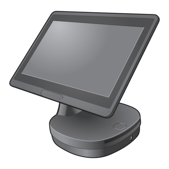
INTRODUCTION Product Overview The figures in this section illustrate the components (including input and output ports) located at the front and rear of your Touch Terminal. Front View Standard Type Standard with Printer (Optional) Rear View Standard Type Customer Display Type (Optional) Secondary LCD Display Type (Optional) Standard with Printer (Optional) - Page 10 INTRODUCTION I/O Ports ARC-615W/ARC-815W (Standard IO) ARC-615W/ARC-815W (By Project IO) Item Description LAN port Gigabit LAN connector USB2.0 ports USB2.0 connectors HDMI port HDMI Vertical connector USB3.0 ports USB3.0 connectors COM1 port COM connector COM2 port COM connector Power input (DC IN jack) DC power input DK port Cash Drawer output...
-
Page 11: Physical Dimensions
INTRODUCTION Physical Dimensions Customer Display... - Page 12 INTRODUCTION Customer Display with Printer...
- Page 13 INTRODUCTION Secondary LCD Display...
- Page 14 INTRODUCTION Secondary LCD Display with Printer...
-
Page 15: Specifications
INTRODUCTION Specifications Touch Terminal Specifications ARC Series Model number ARC-615W ARC-815W LCD & Touch Panel LCD Panel 15.6” LED-backlit display Resolution 1366 x 768 (default) Brightness 220 cd/m Touch Screen Flat Projected Capacitive Touch System Configuration Intel Skylake U Processors ®... - Page 16 INTRODUCTION ARC Series Model number ARC-615W ARC-815W DC12V out DC24V out Speaker output 1*1W speaker Powering System External 200W External 200W External 65W DC External 65W DC DC Power DC Power Power adapter Power adapter Power Supply adapter adapter AC100 to 240V full range...
-
Page 17: Chapter 2: Preparing For The Installation
PREPARING FOR THE INSTALLATION Chapter 2 Preparing For the Installation Before you start installing Touch Terminal, read the following instructions. • Tango Series do not support PCI slot. • Do not insert or remove any device or component from the Tango Series while the power is turned on. -
Page 18: Main Board Jumper Setting And Connector Definition
PREPARING FOR THE INSTALLATION Main Board Jumper Setting and Connector Definition 615W Top View JUSB1 LOGO1 eDP1 FAN1 EDP_SW1 JUSB2 GPIO1 SPK_R1 SPK_L1 COM3 DC12V1 COM2 AUDIO1 COM1 JUSB3 LAN1 HDMI1 USB12 USB24 USB3_1 CASHDRAW1... - Page 19 PREPARING FOR THE INSTALLATION Connector/Jumper Description COM1 COM connector COM2 COM connector COM3 COM connector CASHDRAW1 Cash Drawer output 24V DC power input DC power output JUSB2 E-SATA + USB connector USB3.0 ports USB3.0 connectors (x2) USB24 24V Powered USB connector USB12 / JUSB3 12V Powered USB connector / USB connect (Select one)
-
Page 20: Bottom View
PREPARING FOR THE INSTALLATION Bottom View SATA1 SO-DIMM1 JP1: Clear CMOS Contents Setting Function Pin 1-2 Short/Closed Normal 1 2 3 Pin 2-3 Short/Closed Clear CMOS JP2: LCD Panel Power Selection Setting Function Pin 1-2 Short/Closed 3.3V 1 2 3 Pin 2-3 Short/Closed JP5: Cash Drawer Power Selection Setting... -
Page 21: 815W Top View
PREPARING FOR THE INSTALLATION 815W Top View SPK_R1 SPK_L1 JUSB1 LOGO1 eDP1 EDP_SW1 FAN1 AUDIO1 / 12V JUSB2 GPIO1 DC12V1 COM3 COM2 COM1 JUSB3 CASHDRAW1 Connector/Jumper Description COM1 connectors COM2 connectors COM3 connectors CASHDRAW1 Cash Drawer output 24V DC power output DC power input JUSB2 USB connector (JST2.0mm 1x5) -
Page 22: Bottom View
PREPARING FOR THE INSTALLATION Connector/Jumper Description DC12V1 12V output connect (JST2.5mm 1x2) SPK_L1 L channel Speaker out (JST2.0mm 1x2) SPK_R1 R channel Speaker out (JST2.0mm 1x2) JUSB2 USB connectors (JST2.0mm-1x5) JUSB1 USB connectors (JST2.0mm-1x7) Power switch connect (JST2.0mm 1x4) LOGO1 Logo power out (JST2.0mm 1x3) EDP_SW1 Filp switch connect (JST2.0mm 1x2) - Page 23 PREPARING FOR THE INSTALLATION JRTC1: Clear CMOS Contents Setting Function Pin 2-3 Short/Closed Normal Default 1 2 3 Pin 1-2 Short/Closed Clear CMOS JP1: LCD Panel Power Selection Setting Function Pin 1-2 Short/Closed 3.3V Default 1 2 3 Pin 2-3 Short/Closed JP2: PS2 Keyboard Voltage selection Setting Function...
-
Page 24: Voltage Output Definition
PREPARING FOR THE INSTALLATION Voltage Output Definition Connector with Voltage Output Location Power Support DC5V/DC12V COM 1 for extension interface (9 PIN of DB-9) Mainboard select by BIOS DC5V/DC12V COM 2 for extension interface (9 PIN of DB-9) Mainboard select by BIOS DC5V/DC12V COM 3 for extension interface (9 PIN of DB-9) -
Page 25: Setting The Lcd Brightness
PREPARING FOR THE INSTALLATION Setting the LCD Brightness To configure the LCD brightness setting, do the following: 1. During the system boot, press <F2> to enter the BIOS Setup Utility. 2. On the Advanced page, select Video Configuration. 3. Select eDP Brightness Control Level. - Page 26 PREPARING FOR THE INSTALLATION 4. Select the desired brightness level setting.
-
Page 27: Setting The Serial Port Voltage
PREPARING FOR THE INSTALLATION Setting the Serial Port Voltage To configure the COM port voltage value, do the following: 1. During the system boot, press <F2> to enter the BIOS Setup Utility. 2. On the Advanced page, select S10 FINTEK F81866A. 3. - Page 28 PREPARING FOR THE INSTALLATION 4. A confirmation message appears on the screen. Press <Enter> to continue. 5. When prompted, enter the password. Then select YES to confirm. NOTE: The default password is "3521".
- Page 29 PREPARING FOR THE INSTALLATION 6. Select the desired voltage value of the designated COM port.
-
Page 30: Setting The Filp-Over Function
PREPARING FOR THE INSTALLATION Setting the Filp-over Function This Touch Terminal is bundled with a software that allows you to let the display to automatically flip its screen orientation as you change the display position. 1. Install the ReversalUtilityInstall software. NOTE: Make sure the software is placed at "C:\"... -
Page 31: Chapter 3: Hardware Installation
HARDWARE INSTALLATION Chapter 3 Hardware Installation Installing the Power Cord, Power Adapter, and Network Cable 1. Remove the connectors cover. 2. Connect the network cable to the LAN port. Then connect the power adapter to the DC IN jack. 3. Align and install the connectors cover. Make sure to push the connectors cover firmly until it clicks into place. -
Page 32: Installing The Customer Display (Optional)
HARDWARE INSTALLATION Installing the Customer Display (Optional) WARNINN: Be sure to turn off the power of the Touch Terminal before making any connection or disconnection. 1. Place the Touch Terminal on a soft and flat surface, with the LCD panel facing down. Then adjust the stand to full upright position. -
Page 33: Installing The Secondary Lcd Display (Optional)
HARDWARE INSTALLATION Installing the Secondary LCD Display (Optional) WARNINN: Be sure to turn off the power of the Touch Terminal before making any connection or disconnection. 1. Remove the connectors cover. 2. Place the Touch Terminal on a soft and flat surface, with the LCD panel facing down. Then adjust the stand to full upright position. - Page 34 HARDWARE INSTALLATION...
-
Page 35: Installing The Magnetic Stripe Reader (Msr) (Optional)
HARDWARE INSTALLATION Installing the Magnetic Stripe Reader (MSR) (Optional) WARNINN: Be sure to turn off the power of the Touch Terminal before making any connection or disconnection. 1. Remove the MSR module compartment cover. 2. Firmly connect the MSR connector into the slot inside the compartment. 3. -
Page 36: Installing The Identification Reader (Optional)
HARDWARE INSTALLATION Installing the Identification Reader (Optional) WARNINN: Be sure to turn off the power of the Touch Terminal before making any connection or disconnection. 1. Remove the connectors cover. 2. Remove the screws securing the dummy cover on the stand arm. 3. - Page 37 HARDWARE INSTALLATION iButton Identification Reader Fingerprint Identification Reader RFID Identification Reader...
- Page 38 HARDWARE INSTALLATION iButton Identification Reader 1. Peel off the Mylar sheet, then disassemble the iButton module kit. Reassemble the kit as shown. Attach the iButton Signal Cable (red) to the end of the iButton using a soldering iron. Attach the iButton Grounding Cable (black) to the washer using a soldering iron. 2.
- Page 39 HARDWARE INSTALLATION Fingerprint Identification Reader 1. Affix the Mylar sheet onto the top stand cover, as shown. 2. Attach the reader module, with sensor area downward, to the top stand cover, as shown. 3. Secure the module with four screws (T2.5*6), as shown. 4.
-
Page 40: Installing The Printer (Optional)
HARDWARE INSTALLATION Installing the Printer (Optional) WARNINN: Be sure to turn off the power of the Touch Terminal before making any connection or disconnection. 1. Remove the connectors cover. 2. Connect one end of the power cable to the DC 24V jack. Then connect one end of the USB or RS232 cable to its respective port on the printer. - Page 41 FREQUENTLY ASKED QUESTIONS (FAQ) Chapter 4 Frequently Asked Questions (FAQ) Question 1: Why does the system appear unstable after updating BIOS? Answer: Load optimized defaults (or load SETUP Default) after flashing BIOS. If the system remains unstable, clear CMOS to solve the problem. To load optimized defaults, do the following: 1.
- Page 42 FREQUENTLY ASKED QUESTIONS (FAQ) 3. Select Yes to save the settings. Question 2: How do I clear CMOS? Answer: To clear CMOS, do the following: 1. Turn off power and pull out the power cord. 2. Insert the jumper cap to clear CMOS PIN and remove the jumper cap from clear CMOS PIN. 3.
Need help?
Do you have a question about the ARC Series and is the answer not in the manual?
Questions and answers