Table of Contents
Advertisement
Quick Links
Advertisement
Table of Contents

Related Manuals for Datavan G-615


Summary of Contents for Datavan G-615
- Page 1 Glamor Series G-615 / G-615S / G-715 / G-715S(R) User Manual Version 1.1...
-
Page 2: About This Manual
About this Manual Thank you for purchasing Glamor Series Touch Terminal. This terminal offers highly enhanced features, with easy connection to various optional devices for optimal performance. This user manual describes how to setup and connect your terminal. Copyright © Copyright 2015 All rights reserved. - Page 3 immediately: The power cord or plug is damaged. Liquid has been spilt on to the equipment. The equipment has been dropped and damaged. The equipment does not function normally. Do not block any ventilation openings to prevent the equipment from overheat. Do not leave the equipment in a non air-conditioned environment where the storage temperature may go above 70°C (158°F), as this can cause damage to the equipment.
- Page 4 Federal Communications (FCC Statement) This device may not cause harmful interference. This device must accept any interference received including interference that may cause undesirable operation. This equipment has been tested and found to comply within the limit of a Class A digital device, pursuant to Part 15 of the FCC Rules.
- Page 5 CB/LVD Statement A Class III equipment with an enclosure made of HB material and using a non-special connector for the a.c./d.c. input has to have a marking stating the following: “Use only power supplies listed in the user instructions” or “For applicable power supplies see user instructions”.
-
Page 6: Table Of Contents
Signal Convergence Board Connector ..........33 Extension I/O Brick Board Connector (For G-715SR only) ................34 ..............35 G-615 / G-715 ...................35 G-615S ......................35 G-715S/G-715SR ..................36 Calibrating the Touch Screen in Windows .......... 37 Setting the LCD Brightness ..............39 G-615 ......................39... - Page 7 Chapter 3: Hardware Installation .......... 44 Adjusting the System Stand ..............44 Installing the Power Cord, Power Adapter, and Network Cable ..46 Installing the Customer Display (Optional) ......... 48 Installing the Secondary LCD Display (Optional) ....... 50 Installing the IG-20L MSR (Optional)............ 54 ....
-
Page 8: Chapter 1: Introduction
INTR ODUCTION Chapter 1 Introduction Congratulations on your purchase of this Touch Terminal. Your easy-to-use POS terminal is Package Contents Before setting up your Touch Terminal, check that the package contains the following items. If any of the items is missing or damaged, contact your vendor immediately. Touch Terminal Accessory Kit Power Cord &... -
Page 9: Overview Of Glamor Series
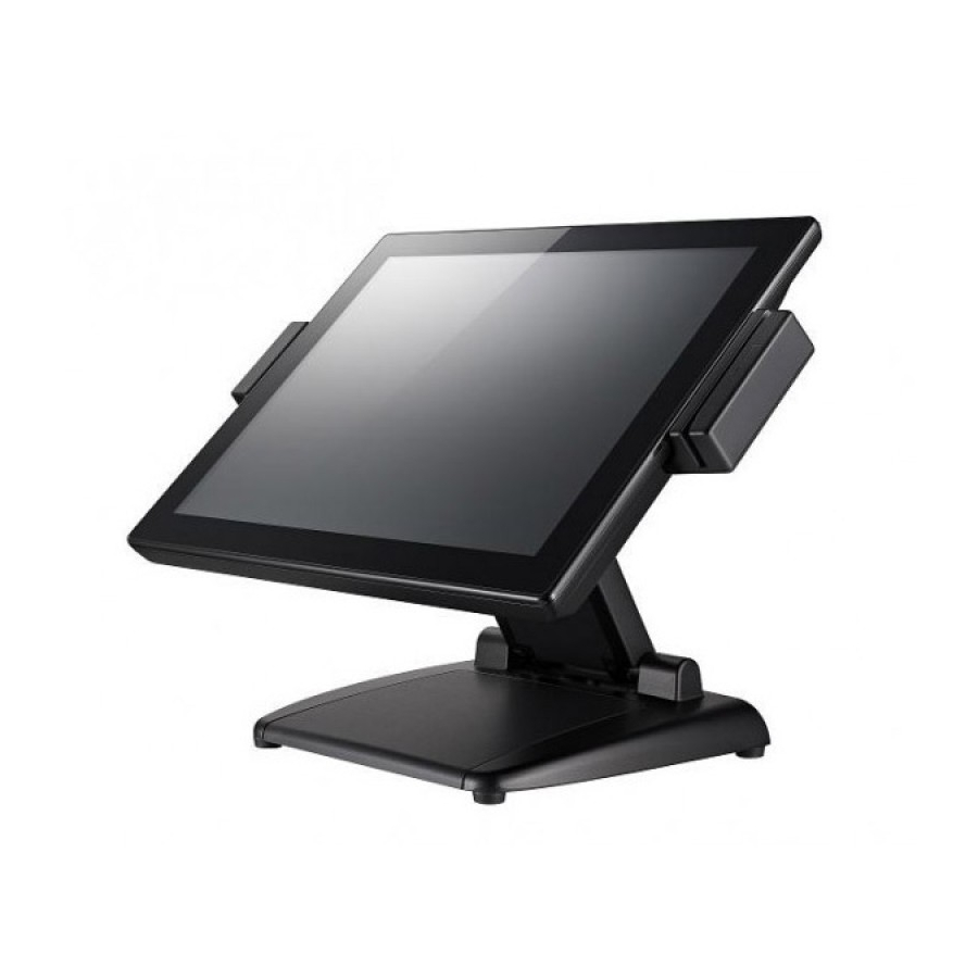
INTR ODUCTION Overview of Glamor Series the front and rear of your Touch Terminal. Front View Standard Type NOTE: Rear View Standard Type Customer Display Type Secondary LCD Display Type NOTE:... - Page 10 INTR ODUCTION I/O Ports G-615 / G-715 G-615S USB 12V USB 12V USB 24V USB COM *for G-715SR only. G-715S(R) Item Description 12V DC power output 24V DC power input COM ports COM connectors K/B port PS/2 keyboard connector DK port...
-
Page 11: Physical Dimensions
INTR ODUCTION Physical Dimensions Standard Display 360.867 414.95 249.833 414.95 249.833... - Page 12 INTR ODUCTION LCM/VFD Customer Display 290.747...
- Page 13 INTR ODUCTION 8” Secondary LCD Display 349.876 209.954...
- Page 14 INTR ODUCTION Glamor Series Model number G-615 G-615S G-715 G-715S G-715SR LCD & Touch Panel LCD Panel 15” LED-backlit display Resolution 1024 x 768 (default) Brightness 250 cd/m Touch Screen Celeron® Celeron® 2.4GHz Atom™ D525 Celeron® 2.2 GHz J1900 2.0GHz / Core™...
- Page 15 INTR ODUCTION Glamor Series Model number G-615 G-615S G-715 G-715S G-715SR I/O Ports Parallel (option) by cable output USB2.0 USB3.0 eSATAp/USB2.0 combo RJ45 COM Gigabit Ethernet Line out PS/2 keyboard HDMI 1 (Dual 1(Dual cash RJ12 cash cash drawer drawer...
- Page 16 INTR ODUCTION Glamor Series Model number G-615 G-615S G-715 G-715S G-715SR Safety & Environment Product Operation 0°C to 40°C Temperature Storage -25°C to 70°C Temperature Windows XP Windows 7 / Windows XP Windows 7 / POSReady 7 / / WEPOS /...
- Page 17 INTR ODUCTION Vacuum Fluorescent Display (VFD) Model no. CM-7100 Display Method Vacuum Fluorescent Display (VFD) Polarizer color Black Backlight color Yellow green Brightness 500-1000 cd/m2 Display capacity 20 characters x 2 lines Character format 5 x 7 dot matrix, cursor Character type 95 Alphanumeric, 32 International characters Dot size...
- Page 18 INTR ODUCTION 2nd LCD Display Model no. MN-0810 MN-1010 LCD Panel 8” TFT LED backlight 10.4” TFT LED backlight Resolution 800 x 600 Color 262,144 Viewing Angle 140° (H) / 125° (V) 110° (H) / 150° (V) Response Time 25ms (typical) 30ms (typical) Contrast Ratio 500:1 (typical)
- Page 19 INTR ODUCTION Model no. IG-10 Dallas DS1990A compliment / With leading / ending programming iButton Detector function. USB HID Keyboard mode interface Biometric Digital Personal U. are .U 4500B (Optical Type / Blue Light) Module Fingerprint Size: Approx. 57.7mm * 35.8mm*11.0mm Compatible with USB 1.1 / 2.0 Recognizer (Full Speed).
- Page 20 INTR ODUCTION Input Data Nominal input voltage DC24V Input voltage range DC22V~DC26V Buffer time Output Data in Normal Operation Nominal output voltage DC 21.09V ~ 23.31V Output current 2.7A Current limit Charging Charge characteristic Liner mode curve End-of-charge voltage DC12.6V Charge current DC1.35A (C.C.
-
Page 21: Chapter 2: Preparing For The Installation
PREPARING FOR THE INSTALLATION Chapter 2 Preparing For the Installation Before you start installing Touch Terminal, read the following instructions. Glamor Series do not support PCI slot. Do not insert or remove any device or component from the Glamor Series while the power is turned on. -
Page 22: System Default Settings
PREPARING FOR THE INSTALLATION System Default Settings The following is the information on default settings for Touch Terminal serial ports. G-615 COM1 COM2 COM3 COM4 COM5 COM6 IRQ4 IRQ3 IRQ5 IRQ10 IRQ5 IRQ10 G-715 COM1 COM2 COM3 COM4 COM5 COM6... -
Page 23: G-615
PREPARING FOR THE INSTALLATION Main Board Jumper Setting and Connector G-615 Connector/Jumper Description LINE OUT Audio line output connector VGA output connector LAN1 Gigabit LAN connector USB1 USB2.0 *2 connector USB2 USB2.0 *2 connector ESATA1 E-SATA + USB connector CASHDRAW1... - Page 24 PREPARING FOR THE INSTALLATION JP1 COM 1 D-SUB PIN9 VOLTAGE SELECT 1-2 = 0V / RI Default = 0V 1 3 5 3-4 = +5V 5-6 = +12V 2 4 6 JP2 COM 2 D-SUB PIN9 VOLTAGE SELECT 1-2 = 0V / RI Default = 0V 1 3 5 3-4 = +5V...
-
Page 25: G-715
PREPARING FOR THE INSTALLATION G-715 Connector/Jumper Description LINE OUT Audio line output connector VGA output connector LAN1 Gigabit LAN connector USB1 USB2.0 *2 connector USB2 USB2.0 *2 connector ESATA1 E-SATA + USB connector CASHDRAW1 Cash Drawer output PS/2 keyboard connector COM1 COM1 connector COM2... - Page 26 PREPARING FOR THE INSTALLATION JP1 LVDS VOLTAGE SETTING 1-2 = +3.3V Default = Normal 1 2 3 2-3 = +5V JP2 Keyboard VOLTAGE SETTING 1-2 = 5VSB Default = Normal 1 2 3 2-3 = +5V JP3 CASH DRAWER VOLTAGE SETTING 1-2 = +24V Default = Normal 1 2 3...
-
Page 27: G-615S
PREPARING FOR THE INSTALLATION G-615S Top View... - Page 28 PREPARING FOR THE INSTALLATION Bottom View Connector/Jumper Description HDMI Vertical connector COM1 connector Gigabit LAN connector COM1 connector COM2 connector COM3 connector USB3.0 *2 connector USB2.0 *2 connector Cash Drawer output PS/2 keyboard connector CON10 12V DC power output CON11 E-SATA + USB connector CON12 24V DC power input...
- Page 29 PREPARING FOR THE INSTALLATION Connector/Jumper Description Power Button Connector Mini PCIE V1.2 Connector SPI Flash Tool Connector (Factory use only) JP2 ME CLEAR JUMPER 1-2 = Normal Default = Normal 1 2 3 2-3 = ME clear JP3 CMOS CLEAR JUMPER 1-2 = Normal Default = Normal 1 2 3...
-
Page 30: G-715S/G-715Sr
PREPARING FOR THE INSTALLATION JP9 COM 1 D-SUB PIN9 VOLTAGE SELECT 1-2 = 0V / RI Default = 0V 1 3 5 3-4 = +5V 5-6 = +12V 2 4 6 JP12 Keyboard VOLTAGE SETTING 1-2 = 5VSB Default = Normal 1 2 3 2-3 = +5V JP13 CASH DRAWER VOLTAGE SETTING... - Page 31 PREPARING FOR THE INSTALLATION Bottom View Connector/Jumper Description Audio line output connector VGA output connector Gigabit LAN connector USB3.0 *2 connector USB2.0 *2 connector USB2.0 Vertical connector E-SATA + USB connector Cash Drawer output PS/2 keyboard connector CON10 HDMI Vertical connector CON11 COM1 connector CON12...
- Page 32 PREPARING FOR THE INSTALLATION Connector/Jumper Description SATA Connector (J8 Pin7 Setting by JP8 for SATA DOM) M/B Signal convergence connector SPI Flash Tool Connector (Factory use only) SATA3.0 2.5” HDD/SSD 7+15PIN Dock Mini PCIE V1.2 Connector System Function Connector J14 / J15 DDR3/DDR3L SO-DIMM Fan2 Power Connector JP2 CMOS CLEAR JUMPER...
-
Page 33: Signal Convergence Board Connector
LED backlight inverter connector SPK_L1 Speaker connector SPK_R1 Speaker connector connector to Power switch (optional) LVDS1 2x15 LVDS connector COM5 connector for RS-232 POS input device for G-615 / G-715 COM6 connector for RS-232 POS input device for G-615S / G-715S... -
Page 34: Extension I/O Brick Board Connector (For G-715Sr Only)
PREPARING FOR THE INSTALLATION Extension I/O Brick Board Connector (For G-715SR only) Connector/Jumper Description USB signal input COM4 signal input COM 4 D-SUB PIN9 VOLTAGE SELECT COM4 connector 24V Powered USB connector 12V Powered USB connector 12V Powered USB connector USB 2.0 Vertical connector JP1 COM 4 D-SUB PIN9 VOLTAGE SELECT 1-2 = 0V... -
Page 35: G-615 / G-715
PREPARING FOR THE INSTALLATION G-615 / G-715 Connector with Voltage Output Location Power Support DC5V/DC12V COM 1 for extension interface (9 PIN of DB-9) Main Board DC5V/DC12V COM 2 for extension interface (9 PIN of DB-9) Main Board DC5V/DC12V COM 3 for extension interface (9... -
Page 36: G-715S/G-715Sr
PREPARING FOR THE INSTALLATION G-715S/G-715SR Connector with Voltage Output Location Power Support DC5V/DC12V COM 1 for extension interface (9 PIN of DB-9) Main Board DC5V/DC12V COM 2 for extension interface (9 PIN of DB-9) Main Board DC5V/DC12V COM 3 for extension interface (9 PIN of DB-9) Main Board DC5V/DC12V... -
Page 37: Calibrating The Touch Screen In Windows
PREPARING FOR THE INSTALLATION Calibrating the Touch Screen in Windows Setting 1. Beep Touch sound Frequency: Set the sound type Duration: Audio sound length 2. Linearization style Set 9-point or 25-point calibration... - Page 38 PREPARING FOR THE INSTALLATION Tools 1. 4 points calibration The device needs to be calibrated for the touch screen to work accurately. Whenever the touch screen seems inaccurate, recalibrate the screen again. Press this button to display a new window to guide you to do the 4 points calibration. On the calibration window, follow the guide and touch and hold the blinking symbol as it moves around the screen.
-
Page 39: Setting The Lcd Brightness
PREPARING FOR THE INSTALLATION Setting the LCD Brightness G-615 1. Press <F2> when system boot. Select <LPC Control Sub-Menu> item of <Intel> Group. 2. Select <Hardware Monitor> item. -
Page 40: G-715
PREPARING FOR THE INSTALLATION 3. Change <Brightness Control Level> Level for Brightness setting. G-715 <Advanced> Group. - Page 41 PREPARING FOR THE INSTALLATION 3. Change <Brightness Control Level> Level for Brightness setting.
- Page 42 PREPARING FOR THE INSTALLATION G-615S Advanced Main Chipset Boot Security Save & Exit OnBoard LAN PXE Rom Disabled ► ACPI Settings ► LVDS Configuration ► F81866 Super IO Configuration ► Hardware Monitor ► CPU Configuration ► PPM Configuration ► IDE Configuration Advanced Main Chipset...
-
Page 43: G-715S/G-715Sr
PREPARING FOR THE INSTALLATION G-715S/G-715SR Main Advanced Chipset Boot Security Save & Exit ► PCI Subsystem Settings ► ACPI Settings Select Screen → ← ► Wakeup event Configuration ↑ ↓ Select Item ► CPU Configuration Enter: Select ► SATA Configuration +- Change Field ►... -
Page 44: Chapter 3: Hardware Installation
HARDWARE INSTALLATION Chapter 3 Hardware Installation Adjusting the System Stand CAUTION: Never open the unit unless it is in the lowest horizontal position. Otherwise, system components may be damaged. 1. Place the Touch Terminal on a stable surface and carefully lift the LCD panel. NOTE: with the other hand. - Page 45 HARDWARE INSTALLATION 3. Flip the LCD panel around to face outward. Upper hinge Lower hinge NOTE:...
-
Page 46: Installing The Power Cord, Power Adapter, And Network Cable
HARDWARE INSTALLATION Installing the Power Cord, Power Adapter, and Network Cable Remove the cable compartment and the connectors covers. 2. Route the power adapter and the network cable through the cable compartment. Then connect the network cable to the LAN port, and connect the power adapter to the 24V When removing the power adapter, be sure to hold the... - Page 47 HARDWARE INSTALLATION 3. Align and install the cable compartment and the connectors covers. 4. Connect the power adapter to the power cord. Then plug the other end of the power cord to an electrical outlet. 5. Connect the network cable to connect to a hub or switch. WARNING: s u r e t u r n...
-
Page 48: Installing The Customer Display (Optional)
HARDWARE INSTALLATION Installing the Customer Display (Optional) WARNING: s u r e t u r n o ff t h e p o w e r o f t h e To u c h Te r m in a l b e f o r e a k in g a n y c o n n e c t io n... - Page 49 HARDWARE INSTALLATION 3. Route the customer display’s interface cable on the left side of the cable compartment of the customer display's bracket, as shown in the illustration below. 4. Install the customer display bracket into its slot on the back of the LCD panel. Make sure the bracket is properly aligned with the hinge.
-
Page 50: Installing The Secondary Lcd Display (Optional)
HARDWARE INSTALLATION 6. Align and install the connectors cover. Installing the Secondary LCD Display (Optional) WARNING: Be sure to turn off the power of the Touch Terminal before making any connection or disconnection. Remove the connectors cover. - Page 51 HARDWARE INSTALLATION 2. Remove the two screws (F M4x10) on the hinge cover. Then remove the hinge cover. 3. Remove the secondary LCD display compartment.
- Page 52 HARDWARE INSTALLATION 4. Install the secondary LCD display into its slot on the bracket. Then secure the customer display to the bracket with the two screws (F M4x6.5) and replace the secondary LCD display compartment. 5. Route the secondary LCD display’s power cable, VGA cable, and Touch USB cable (optional) on the cable compartment of the bracket, as shown in the illustration below.
- Page 53 HARDWARE INSTALLATION 6. Install the secondary LCD display bracket into its slot on the back of the LCD panel. Make sure the bracket is properly aligned with the hinge. Then secure the bracket to the hinge with the two screws (F M4x10). 7.
-
Page 54: Installing The Ig-20L Msr (Optional)
HARDWARE INSTALLATION 8. Align and install the connectors cover. Installing the IG-20L MSR (Optional) WARNING: s u r e t u r n o ff t h e p o w e r o f t h e To u c h Te r m in a l b e f o r e a k in g... - Page 55 HARDWARE INSTALLATION 2. Press the latch down to disengage the MSR module cover from its main unit. Then remove the MSR module cover. 3. Firmly connect the MSR connector into the slot inside the compartment. 4. Secure the MSR module to the Touch Terminal, using the two screws (M3x8).
- Page 56 HARDWARE INSTALLATION 5. Install the MSR module cover. (Optional) WARNING: Be sure to turn off the power of the Touch Terminal before making any connection or disconnection. 1. Remove the reader compartment.
- Page 57 HARDWARE INSTALLATION 2. Firmly connect the reader connector into the slot inside the compartment. 3. Press the latch down to disengage the reader cover from its main unit. Then carefully pull the cover by the left side to release it from its main unit. WARNING:...
- Page 58 HARDWARE INSTALLATION 4. Secure the reader to the Touch Terminal, using the two screws (M3x8). NOTE: 5. Install the reader cover.
-
Page 59: Installing The Secondary Hard Disk Drive (Optional)
HARDWARE INSTALLATION Installing the Secondary Hard Disk Drive (Optional) WARNING: s u r e t u r n o ff t h e p o w e r o f t h e To u c h Te r m in a l b e f o r e a k in g a n y... - Page 60 HARDWARE INSTALLATION the other hand. 4. Install the HDD bracket into its slot on the stand cover, as shown in the illustration below. Then secure the HDD bracket to the stand cover with the four screws (M3x6). the stand cover onto the stand.
- Page 61 HARDWARE INSTALLATION 6. Remove the cable compartment and the connectors covers. 7. Route the eSATAp to SATA 22pin cable through the cable compartment. Then connect the other end of the eSATAp to SATA 22pin cable to the E-SATAp port. 8. Align and install the cable compartment and the connectors covers.
-
Page 62: Installing The Wireless Module (Optional)
HARDWARE INSTALLATION Installing the Wireless Module (Optional) WARNING: Be sure to turn off the power of the Touch Terminal before making any connection or disconnection. the other hand. 2. Install the wireless module into its slot on the stand cover, as shown in the illustration below. Then secure the cable bracket to the stand cover with the two screws (F M3x4). - Page 63 HARDWARE INSTALLATION 4. Remove the cable compartment and the connectors covers. 5. Route the wireless module cable through the cable compartment. Then connect the wireless module cable to the USB port. 6. Align and install the cable compartment and the connectors covers.
-
Page 64: Installing The Ups Kit (Optional)
HARDWARE INSTALLATION 7. Plug the Wi-Fi dongle onto the USB port of the wireless module. Installing the UPS Kit (Optional) WARNING: s u r e t u r n o ff t h e p o w e r o f t h e To u c h Te r m in a l b e f o r e... - Page 65 HARDWARE INSTALLATION 3. Connect the one end of the power cable to the 4-pin Then route the other end of the of the power cable and one end of the power adapter through the cable compartment as shown in the illustration. 4.
-
Page 66: Installing The Vesa Mount (Optional)
HARDWARE INSTALLATION 6. Align and install the cable compartment and the connectors covers. Installing the VESA Mount (Optional) NOTE: Remove the two screws (F M4x10) on the hinge cover. Then remove the hinge cover. - Page 67 HARDWARE INSTALLATION 2. Remove the four screws (M4x12) on the hinge. Then remove the stand. 3. Align and install the VESA plate on the back of the Touch Panel using four screws (F M4x10). 4. Attach the mount bracket onto the VESA plate using four screws (M4x10).
- Page 68 HARDWARE INSTALLATION 5. Drill four small holes on the mounting location and insert the plastic washers into the holes. Then place the four supplied screws into the four holes at the wall bracket, and secure them into the holes on the wall. 6.
-
Page 69: Chapter 4: Frequently Asked Questions (Faq)
Frequently Asked Questions (FAQ) Question 1: Why does the system appear unstable after updating BIOS? G-615 / G-715 Answer: system remains unstable, clear CMOS to solve the problem. Steps: On the <Exit> page, select <Load Setup Defaults>, then select <Yes>. - Page 70 FREQUENTLY ASKED QUESTIONS (FAQ) G-615S Answer: system remains unstable, clear CMOS to solve the problem. Steps: On the <Save & Exit> page, select <Restore Defaults>, then select <Yes>. Select <Save Changes and Reset>, and then <Yes> to save the settings. Main Advanced Chipset Boot Security Save &...
-
Page 71: Question 2: How Do I Clear Cmos
FREQUENTLY ASKED QUESTIONS (FAQ) Question 2: How do I clear CMOS? G-615 Answer: To clear CMOS, do the following: 1. Turn off power and pull out the power cord. clear CMOS PIN. 3. Switch on the power again. 4. Press F2 to enter CMOS setting and load optimized defaults. - Page 72 FREQUENTLY ASKED QUESTIONS (FAQ) G-715 Answer: To clear CMOS, do the following: 1. Turn off power and pull out the power cord. clear CMOS PIN. 3. Switch on the power again. 4. Press F2 to enter CMOS setting and load optimized defaults. 5.
- Page 73 FREQUENTLY ASKED QUESTIONS (FAQ) G-615S Answer: To clear CMOS, do the following: 1. Turn off power and pull out the power cord. clear CMOS PIN. 3. Switch on the power again. 4. Press F2 to enter CMOS setting and load optimized defaults. 5.
-
Page 74: Question 3: How To Use Boot Menu
FREQUENTLY ASKED QUESTIONS (FAQ) G-715S /G-715SR Answer: To clear CMOS, do the following: 1. Turn off power and pull out the power cord. clear CMOS PIN. 3. Switch on the power again. 4. Press F2 to enter CMOS setting and load optimized defaults. 5.
Need help?
Do you have a question about the G-615 and is the answer not in the manual?
Questions and answers