Subscribe to Our Youtube Channel
Summary of Contents for AGA FFD
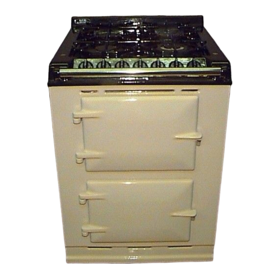
- Page 1 2 BURNER GAS HOB OPTION (FFD) (For use in 4 Oven Aga Cookers Only) Installation Instructions LEAVE WITH CUSTOMER THIS PRODUCT IS NOT RETROFITABLE PLEASE READ THESE INSTRUCTIONS BEFORE INSTALLING THIS APPLIANCE For use in GB and IE 04/07 EINS 512048...
- Page 2 CONTENTS SECTION PAGE GENERAL REQUIREMENTS SPECIFICATIONS TECHNICAL DATA INSTALLATION SEQUENCE & PROCEDURE 6-14...
- Page 3 GENERAL REQUIREMENTS IMPORTANT PLEASE READ THROUGH COMPLETELY BEFORE COMMENCING INSTALLATION. WARNING: THIS APPLIANCE SHALL BE INSTALLED IN ACCORDANCE WITH THE REGULATIONS IN FORCE AND ONLY USED IN A WELL VENTILATED SPACE, READ THE INSTRUCTIONS BEFORE INSTALLING OR USING THIS APPLIANCE. PRIOR TO INSTALLATION, ENSURE THAT THE LOCAL DISTRIBUTION CONDITIONS (TYPE OF GAS AND GAS PRESSURE) AND THE ADJUSTMENTS OF THE APPLIANCE ARE COMPATIBLE.
- Page 4 SPECIFICATIONS REAR GAS INLET HOLE SIDE ELECTRICAL CONNECTION POSITION (HOB UNIT) HOLE (HOB UNIT) 1487 1340 REAR ENTRY - ELECTRICAL CONNECTION 1125 SIDE ENTRY - ELECTRICAL CONNECTION Fig. 2 DESN 512066 A COOKER DIMENSIONS When surveying for a cooker installation the actual clearance required for the ‘body’ of the appliance should be increased overall by 10mm beyond the figures quoted.
- Page 5 TECHNICAL DATA NATURAL GAS - G20 (APPLIANCE CATEGORY 1 FRONT BURNER REAR BURNER BURNER TYPE SEMI-RAPID RAPID MAXIMUM HEAT INPUT 1.75kW 3.25kW INJECTOR MARKING PRESSURE POINT POSITION: INJECTOR OF REAR BURNER PRESSURE SETTING: 20mbar BURNER IGNITION: H.T. SPARK PROPANE G31 - (APPLIANCE CATEGORY 1 FRONT BURNER REAR BURNER BURNER TYPE...
- Page 6 11. One, 25mm M3 screw 24. Fitting kit - burner tray (AG4M211601) This appliance is designed for use only with Aga four oven models and must be fitted in the top casting above the hot cupboard. 1. Proceed with the main Aga build in accordance with normal practice. Build up to top-plate level.
- Page 7 Isolate the gas supply and connect 8mm diameter pipework up to the approximate position for final connection to the hob unit. (See Fig. 4). REAR ENTRY GAS PIPE SIDE ENTRY GAS PIPE Fig. 4 DESN 512062 Prepare the route for the electrical cable as follows:- (Refer to wiring diagram Fig.
- Page 8 Non-Electric Agas only - Fit 2 layers of insulation blanket JPAD210722 (supplied with hob) on top of the oven roof. (See Fig. 6). Fig. 6 DESN 511733 Electric Aga - Fit one-off insulation blanket JPAD210722 (supplied with hob) on top of oven roof. (See Fig. 7). Fig. 7 DESN 511734...
- Page 9 If not, adjustment should be made to the hotcupboard position. Shim under the hotcupboard base if necessary. 10. Levelling of the simmering plate on the main Aga cooker can be carried out with its top plate in position and verified across the hotcupboard (See Fig. 9).
- Page 10 Complete the main cooker build and loosely screw down the top plate. 12. (a) Remove Gas Hob from box. Disconnect electrical supply cable from hob chassis. (Unscrew wires from terminal strip and slacken screw in cable clamp). Feed electrical cable supply in through appropriate grommets in hotcupboard. (Ensuring cable does not become tangled).
- Page 11 18. Connect electrical cable to a fused double pole switch, as described in General Requirements. Fuse Rating - 3 amps Cable Colour Coding Brown - Live Blue - Neutral Green/Yellow - Earth 19. Locate the two stainless steel spring plates on the underside of the hob surface plate glass.
- Page 12 21. Attach two fixing disc gaskets to the two fixing discs (one for each burner size). (See Fig. 14). Fig. 14 DESN 512055 22. Attach two fixing discs to the hob using 4 (M3) fitting screws (2 for each burner). (See Fig. 15).
- Page 13 24. PRESSURE TESTING (SEE FIG. 16). The pressure test point is situated at the injector of the rear burner (rapid). Fig. 16 DESN 513606 Fit the pressure gauge onto the burner injector/pressure test point. Place the semi-rapid burner cap into position on the hob (align holes with the burner electrode and thermocouple tip).
- Page 14 25. Verify that the top plates are level. 26. Secure handrails as shown on Instruction Sheet EINS 511080. 27. Tighten main Aga top plate, and fix hotcupboard top plate into place using the four tap plate retaining screws. Finally screw chrome buttons into place.
- Page 16 For further advice or information contact your local distributor/stockist With Aga’s policy of continuous product improvement, the Company reserves the right to change specifications and make modifications to the appliance described and illustrated at any time. Manufactured By Station Road...


Need help?
Do you have a question about the FFD and is the answer not in the manual?
Questions and answers