Table of Contents
Advertisement
Quick Links
Ransburg
MODEL: A11515-XXXXX
PULSETRACK
SPEED CONTROL AND
MONITOR SYSTEM
IMPORTANT: Before using this equipment,
carefully read SAFETY PRECAUTIONS, starting
on page 1, and all instructions in this manual.
Keep this Service Manual for future reference.
SERVICE MANUAL
LN-9248-05.3
(Replaces LN-9248-05.2)
March - 2013
Service Manual Price:
€25.00 (Euro)
$30.00 (U.S.)
Advertisement
Table of Contents

Summary of Contents for Ransburg Pulsetrack 2
- Page 1 Ransburg SERVICE MANUAL LN-9248-05.3 (Replaces LN-9248-05.2) March - 2013 PULSETRACK SPEED CONTROL AND MONITOR SYSTEM MODEL: A11515-XXXXX IMPORTANT: Before using this equipment, carefully read SAFETY PRECAUTIONS, starting on page 1, and all instructions in this manual. Keep this Service Manual for future reference.
- Page 2 NOTE: This manual has been changed from revision LN-9248-05.2 to revision LN-9248-05.3. Reasons for this change are noted under “Manual Change Summary” on page 53 of this manual.
-
Page 3: Table Of Contents
CONTENTS PAGE SAFETY: SAFETY PRECAUTIONS......................HAZARDS / SAFEGUARDS...................... INTRODUCTION: 6-10 GENERAL DESCRIPTION......................A11515 PULSETRACK 2 SPEED CONTROL AND MONITOR SYSTEM MODEL IDENTIFICATION..............SPECIFICATIONS........................TYPICAL TURBODISK 2 INSTALLATION WITH TEMPERATURE HUMIDITY CARDS..................ELECTRICAL NOISE........................INSTALLATION: 11-26 11-12 LOCATION..........................12-13 INPUT POWER........................... - Page 4 CONTENTS (Cont.) PAGE PARTS IDENTIFICATION: 45-52 CONTROL PANEL - FRONT VIEW / PARTS LIST..............45-46 CONTROL PANEL - INSIDE DOOR VIEW / PARTS LIST............47-48 CONTROL PANEL - INSIDE CABINET VIEW / PARTS LIST..........49-50 RECOMMENDED SPARE PARTS LIST................... WARRANTY POLICIES: LIMITED WARRANTY.........................
-
Page 5: Safety
Safety Section in this manual and the understand all of the technical and safety liter- Ransburg safety literature therein identified. ature for your Ransburg products. This manual contains information that is important for you to † This manual MUST be read and thor- know and understand. -
Page 6: Hazards / Safeguards
AREA HAZARD SAFEGUARDS Tells where hazards Tells what the hazard is. Tells how to avoid the hazard. may occur. Spray Area Fire Hazard Improper or inadequate Fire extinguishing equipment must be present in operation and maintenance the spray area and tested periodically. procedures will cause a fire Spray areas must be kept clean to prevent the hazard. - Page 7 AREA HAZARD SAFEGUARDS Tells where hazards Tells what the hazard is. Tells how to avoid the hazard. may occur. Explosion Hazard Spray Area Electrostatic arcing must be prevented. Safe Improper or inadequate oper- sparking distance must be maintained between ation and maintenance proce- the parts being coated and the applicator.
- Page 8 AREA HAZARD SAFEGUARDS Tells where hazards Tells what the hazard is. Tells how to avoid the hazard. may occur. Spray Area / Electrical Discharge High Voltage Parts being sprayed and operators in the spray There is a high voltage device Equipment area must be properly grounded.
- Page 9 AREA HAZARD SAFEGUARDS Tells where hazards Tells what the hazard is. Tells how to avoid the hazard. may occur. Electrical Electrical Discharge Equipment Unless specifically approved for use in hazard- High voltage equipment is uti- ous locations, the power supply, control cabinet, lized in the process.
-
Page 10: Introduction General Description
The basic components of the PulseTrack 2 system that atomizer. are described below. Temperature/Humidity Card... -
Page 11: A11515 Pulsetrack 2 Speed Control And Monitor System Model Identification
Brake valves to the Control card for processing. are not used for Turbodisk rotators. A11515 PULSETRACK 2 SPEED CONTROL AND MONITOR SYSTEM MODEL IDENTIFICATION When ordering, use A11515-ABCDE: Model No. A11515 - A... -
Page 12: Specifications
SPECIFICATIONS Pneumatic Inputs Environmental / Physical Supply Air: 1/4" ID x 3/8" OD 110 psi (7.6 bar) maximum, Operating operating Temperature: 0°C to 50°C 80 psi (5.5 bar) minimum, operating Storage 40 micron filtration Temperature: -20°C to 85°C Pressure Switches Humidity: 0 to 95% non-condensing (Enable Inputs):... -
Page 13: Typical Turbodisk 2 Installation With Temperature Humidity Cards
Figure 1: Typical Turbodisk 2 Installation With Temperature Humidity Cards... -
Page 14: Electrical Noise
ELECTRICAL NOISE maximum noise immunity the cabling must contain overall foil and braided shields and be terminated in a continuous 360° manner as previously de- scribed. Special fittings have been provided on Electrical noise refers to stray electrical signals the control panel for termination of these cables in the atmosphere at various signal strengths and frequencies that can affect the operation where they enter the cabinet. -
Page 15: Installation Location
LA0042 Air Manifold Assembly (supplied separately) as follows (see Figure 3): W A R N I N G The PulseTrack 2 Control Panel MUST 1. Remove the turbine air volume booster from > the manifold by loosening the swivel fitting. -
Page 16: Input Power
Figure 3: Optional Brake Control Valve Assembly (Bell Systems Only) Temperature/Humidity Probe(s) the AC Power opening in the top left corner of the control panel. For greatest noise immunity the AC (Optional) input should be located as close as possible to the AC line filter (see Figure 4). -
Page 17: Fiber Optic Cable
FIBER OPTIC CABLE All pneumatic connections are made to the right (See Figure 5) side of the PulseTrack 2 control panel. System components should be installed to minimize the Remove the fitting from the fiber optic input port length of pneumatic control lines. This will max- (FO1 - FO6) on the side of the control panel and imize the rotator speed control response. - Page 18 1/4" OD tubing from the activation source to the Enable input on the right side of the control panel. Typically, the pneumatic Enable input is used to interface with an Ransburg Air Logic Panel. (See the appropriate service manual for further information.)
- Page 19 TABLE 2 - PNEUMATIC CONNECTIONS From Description Supply Factory Air (clean and dry) Supply Air to PulseTrack 2 Rotator 1 Volume Booster Pilot Rotator 1 Transducer Output Control Signal Rotator 2 Volume Booster Pilot Rotator 2 Transducer Output Control Signal...
- Page 20 Special noise reduction connectors have been provided at the top of the PulseTrack 2 control panel for routing of all electrical I/O (see Figure 8). Signals specific to an individual rotator can be...
- Page 21 Figure 6: Electrical I/O Breakout Terminal Locations...
- Page 22 Figure 7: Control Panel Schematic...
- Page 23 Figure 9B: Stripping Of I/O Cable Figure 8: Electrical I/O Connectors Figure 9A: Cable Grommet Hardware...
- Page 24 Inputs For 4-20mA input signals, the following equation can be used to determine the mA input signal Analog Speed Setpoint Inputs corresponding to a given speed: Analog speed setpoint inputs are available for rotators 1 through 6 at breakout terminals J2-A1 through J2-A6.
- Page 25 Master Underspeed Output setpoint input or temperature input depending A 24VDC discreet output exists at breakout termi- on the configuration of the PulseTrack 2 system. nal J3-C22 to indicate when an underspeed fault occurs on any rotator. Using this active high output...
-
Page 26: Electrical I/O
Master Overspeed Output Brake Outputs (Optional, Bells Only) A 24VDC discreet output exists at breakout 24VDC brake outputs are located at breakout ter- terminal J3-C23 to indicate when an overspeed minals J3-C25 through J3-C30. For bell systems fault occurs on any rotator. Using this output in configured with the brake option, these outputs conjunction with the individual rotator fault output it send 24VDC to the brake solenoids when bell... - Page 27 TABLE 5 - ELECTRICAL I/O (Cont.) Breakout Terminal Type Description J3-C19 Active Low (Maintained) Rotator 5 Enable Input J3-C20 Active Low (Maintained) Rotator 6 Enable Input J3-C14 Active Low (Maintained) Master Enable Input J3-C13 Active Low (Momentary) Master Reset Input J4-B1 4-20mA Slot 7 Temperature Input...
-
Page 28: Dip Switch Settings
Figure 10: Control Card DIP SWITCH SETTINGS Dip Switch SW1-1 This dip switch can be used with bell systems configured for optional brake control. When this dip switch is on, brake air is applied to assist in Control Card bringing the bell to a stop when speed control is There is an 8 position dip switch SW1 located turned off, as well as when decreases in operating near the bottom of the control card (see Figure... - Page 29 These dip switches set the board for use with the desired rotator and are factory set according to 3. Secure the cabinet door and turn AC power the PulseTrack 2 ordering configuration (see Table back on. 7). The control card reads these dip switches and adjusts the PID control to the optimum settings for the rotator in use.
- Page 30 NOTE >The AC power must be cycled for the new dip switch setting to be recognized. TABLE 7 - ATOMIZER CARD SW2 DIP SWITCH SETTINGS Maximum Ordering SW2-2 SW2-4 Speed Rotator Type SW-2-1 SW2-3 Configuration A11515-XXX1X 6" Conical Disk 40,000 rpm A11515-XXX4X 6"...
-
Page 31: Operation
Fiber Optic Re- processed and displayed on the Temperature/ ceiver Module located in the PulseTrack 2 control Humidity Card. panel. The Fiber Optic Receiver Module converts... -
Page 32: Atomizer Card Controls
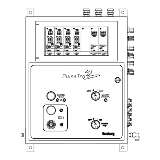
Figure 12: Front Panel Operating Controls ATOMIZER CARD Speed Select Thumbwheel Switch This switch is used in local mode to manually enter CONTROLS the speed control setpoint in thousands of rpms (See Figure 13) (krpm). Press the + or - switch buttons to incre- ment or decrement the desired digit. -
Page 33: Optional Temperature/ Humidity Card Controls
OPTIONAL Local/Remote Switch TEMPERATURE/ When the local/remote switch is in the local posi- tion, the setting on the Speed Select Thumbwheel HUMIDITY CARD switch is used to determine the speed output (see "Local Mode Operation" in the "Operation" section). CONTROLS When this switch is in the remote position, the (See Figure 14) analog speed setpoint inputs are used to determine... -
Page 34: To Enable Speed Control
TO ENABLE SPEED 2. Turn the front panel Power ON/OFF switch to the ON position. CONTROL 3. Move the local/remote switch on the Atomizer Card to the remote position. To enable speed control, first make sure the Pulse- Track 2 is installed as detailed in the "Installation" 4. -
Page 35: Fault Descriptions
Atomizer Card crocontroller and speed control is active, a Loss of Feedback fault occurs. The PulseTrack 2 system performs a number of operational diagnostics and will automatically stop a rotator in the event that an unsafe or abnormal Invalid Speed Request - In condition exists. - Page 36 NOTES To Reset a Fault Faults can be reset using any of the following methods: 1. Press the Master Reset Switch located on the front panel. 2. Activate the momentary external Master Re- set Input (see "Electrical I/O" in the "Installation" section of this manual).
-
Page 37: Maintenance General
For maintenance of system components other should only be accomplished with specif- than the PulseTrack 2, refer to the appropriate ic test equipment by qualified electronics manual or contact your Ransburg repre-sentative technicians or authorized Ransburg repre- or Ransburg Customer Service. - Page 38 3. Open the small glass door and loosen the 5. To replace a switch or indicator, remove the mounting screws on the front of the card. nut from the back of the switch or indicator and remove the part from the door panel. 4.
- Page 39 5. Remove the power supply from the unit and replace with a new one, reconnecting the wires as follows: Wire From Color TB3-Ground Green/Yellow TB1-1 SW1-B3 Light Blue TB1-2 SW1-A4 Black TB1-3 SW1-X1 Dark Blue TB2-1 TB4-1C Dark Blue TB2-2 SW1-X2 Dark Blue TB2-3...
- Page 40 8. Mount the new transducer using the two mount- Fiber Optic Receiver Module ing screws. 1. Turn off AC Power to the control panel at the Fused Disconnect and open the cabinet door. 9. Reinstall the manifold assembly in reverse order of disassembly.
- Page 41 Brake Solenoid (bells only - refer to Figures 6, 16, and 19) From Wire ID 1. Turn off AC Power to the control panel at the Fused Disconnect and open the cabinet door. TB4-4D SOL1-Bottom J3-25C SOL1-Top 2. Turn off supply air to the cabinet and bleed off TB4-5D SOL2-Bottom pressure.
-
Page 42: Troubleshooting
Field repair and troubleshooting of the > and the “Operation” and “Parts Identification” sec- PulseTrack 2 Control Panel may require tions of this manual. The following section outlines exposure to potentials that can cause the most common problems encountered and... - Page 43 the system the problem lies. If the same problem Overspeed (oS) Fault: is occurring on more than one rotator, inspect 1. The braking air solenoid is not functioning those system elements that are common to all properly. the problem rotators. This includes the air supply pressure to the control panel as well as the re- 2.
-
Page 44: (Continued On Next Page)
TROUBLESHOOTING GUIDE General Problem Procedure Solution No Power 1. 115/230 VAC source 1. Set 24VDC power supply source switch to (Green Power Switch switch on 24VDC power proper position. Light Does Not Come supply set to wrong position On and Displays Are Blank) 2. - Page 45 TROUBLESHOOTING GUIDE (Cont.) General Problem Procedure Solution 1. Pneumatic or electrical 1. Verify that there is a rotator enable air MASTER RUN enable input missing or signal to the corresponding enable input Switch Is Turned To defective (EN1-EN6) on the side of control panel or RUN, But The Rota- a rotator enable electrical signal to the cor- tor(s) Do Not Turn...
- Page 46 TROUBLESHOOTING GUIDE (Cont.) General Problem Procedure Solution UNDERSPEED 3. Improper rotator type DIP 3. Verify that the proper rotator type is selected Fault (uS) (Cont.) switch setting on Atomizer on the Atomizer Card DIP switches (see Card Table 7). 4. Failing rotator or restricted 4.
- Page 47 TROUBLESHOOTING GUIDE (Cont.) General Problem Procedure Solution 3. Defective Fiber Optic Re- 3. Check the red speed feedback LED located LOSS OF FEEDBACK ceiver Module, cable or on the Fiber Optic Receiver Module for the Fault (LF) (Cont.) transmitter channel in question. The LED should come on if the turbine rotates when enabled.
- Page 48 TROUBLESHOOTING GUIDE (Cont.) General Problem Procedure Solution 1. Improper DIP switch and/ 1. Correct settings (see Tables 4 and 6). Analog Inputs or or jumper settings on Outputs Not Working Control Card. Properly 2. Defective analog input 2. Repair or replace input source. source (remote mode).
-
Page 49: Parts Identification
PARTS IDENTIFICATION Figure 17: Control Panel - Front View... -
Page 50: Control Panel - Front View / Parts List
CONTROL PANEL - FRONT VIEW - PARTS LIST (Figure 17) Item # Part # Description Notation A11515-XXXXX PulseTrack 2 Speed Control and Monitor System Atomizer Card: A11448-00 For A11515-XXX1X, 6" Conical Disk A11448-03 For A11515-XXX2X, Standard Aerobell For A11515-XXX8X, Standard Aerobell... - Page 51 Figure 18: Control Panel - Inside Door View...
-
Page 52: Control Panel - Inside Door View / Parts List
CONTROL PANEL INSIDE DOOR VIEW - PARTS LIST (Figure 18) Item # Part # Description Notation A11471-00 Ribbon Cable Assembly LSME0013-00 Block Holder, Single SW2, SW3, R LSME0005-00 Contact Block, Normally Open SW1, SW2, SW3 75763-00 Pilot Light Bulb, 24VDC SW1, R LSME0007-00 Pilot Light Block... - Page 53 Figure 19: Control Panel - Inside Cabinet View...
-
Page 54: Control Panel - Inside Cabinet View / Parts List
CONTROL PANEL - INSIDE CABINET VIEW - PARTS LIST (Figure 19) Item # Part # Description Notation 4131-11 Fuse, 3A, 250V, Time Delay, 3AG, for A11515-XX0XX, 120 VAC Input F1, F2 4131-03 Fuse, 1.5A, 250V, Time Delay, 3AG, for A11515-XX1XX, 240VAC Input F1, F2 A11466-01 24VDC Power Supply, for A11515-XX0XX,... -
Page 55: Recommended Spare Parts List
RECOMMENDED SPARE PARTS LIST Total # of Control Panels Item # Part # Description A11448-XX* Atomizer Card PCB Assembly — A11547-00 Brake Valve Assembly (optional - bells only) — SMC-424-X* Fiber Optic Cable Assembly 75763-00 Indicator Bulb, 24VDC 4131-XX* Fuse A11466-XX* 24VDC Power Supply 10979-XX*... -
Page 56: Warranty Policies Limited Warranty
THIS WARRANTY IS TO REPLACE PARTS THAT HAVE FAILED BECAUSE OF FAULTY WORKMANSHIP OR MATERIALS. THERE ARE Ransburg will replace or repair without charge any NO IMPLIED WARRANTIES NOR WARRANTIES part and/or equipment that falls within the specified OF EITHER MERCHANTABILITY OR FITNESS time (see below) because of faulty workmanship FOR A PARTICULAR PURPOSE. - Page 57 MANUAL CHANGE SUMMARY This manual was published to replace Service Manual LN-9248-05.2 PulseTrack 2 Speed Control and Monitor System, to make the fol- lowing changes: 1. Added item 8, "The red LED.." to Control Card desciption on page 5. 2. Changed color of LED1 from green to red on...
- Page 58 Telephone: 800/ 233-3366 Fax: 419/ 470-2071 Technical Support Representative will direct you to the appropriate telephone number for ordering Spare Parts. Form No.LN-9248-05.3 © 2013 Ransburg. All rights reserved. Litho in U.S.A. Models and specifications subject to change without notice. 03/13...
Need help?
Do you have a question about the Pulsetrack 2 and is the answer not in the manual?
Questions and answers