
Related Manuals for Geotech ET Series


Summary of Contents for Geotech ET Series
- Page 1 1500’-3000’ (450 m-925 m) ET/MDPE Tape Water Level Meter (with optional electric rewind) Installation and Operation Manual Rev 08/30/12 Part # 12050339...
-
Page 3: Table Of Contents
Table of Contents Section 1: System Description ………………….…………………………………..…….. 3 Section 2: System Installation ……………………………………………………….……. 6 Section 3: System Operation ……………………….…………………..………………… 7 Section 4: System Maintenance ……………………………………….…………….…… 8 Section 5: System Troubleshooting ……………………….…………….………………... 9 Section 6: System Specifications …………………….……….……………………….….. 10 Section 7: System Schematics ……………………………………………………………. 11 Section 8: Replacement Parts List …………………….……………….…………………... - Page 4 DOCUMENTATION CONVENTIONS This uses the following conventions to present information: An exclamation point icon indicates a WARNING of a situation or condition that could lead to personal injury or death. You should not proceed until you read and thoroughly understand the WARNING message.
-
Page 5: Section 1: System Description
Section 1: System Description Function and Theory The Geotech ET/MDPE Water Level Meter (ET/MDPE) is a portable instrument used to accurately measure water levels in monitoring wells and bore holes. The sensor consists of a stainless steel and PTFE probe attached to a reel-mounted, polyethylene-coated engineer’s tape. - Page 6 System Components Figure 1-1 – Manual Reel Front View Figure 1-2 – Manual Reel Side View...
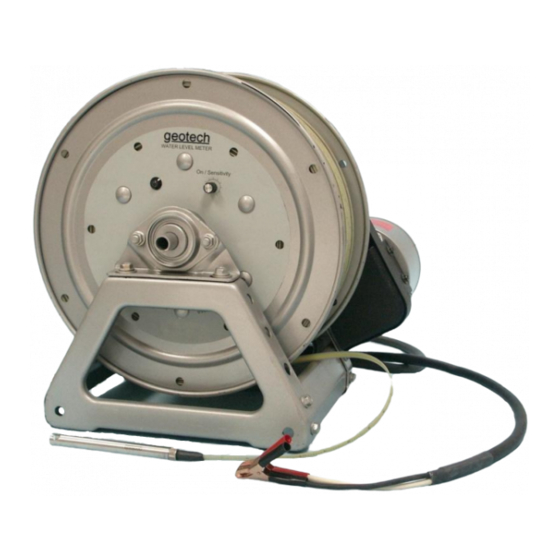
- Page 7 Figure 1-3 – Electric Reel Front View Figure 1-4 – Electric Reel Side View...
-
Page 8: Section 2: System Installation
Section 2: System Installation Manual Reel Carefully lower the probe into the well, using the tape guard to prevent damage to the tape. Do not use the tape guard in wells larger than 4” (10 cm), as it may fall down the well. - Page 9 If you are not able to hang the frame onto the well head, then either use the white plastic leader guard (standard with all units), or the optional Tape Guide, to prevent the edge of the well head from damaging the tape. Figure 2-2 is an example of the two parts Figure 2-1 Tape Leader Guard, Tape Guide and Tape Weight (Optional) Do not use the tape leader guard in wells larger than 4”...
- Page 10 Figure 2-2 Fitting (Optional) Tape Weight Figure 2-3 Tightening (Optional) Tape Weight...
-
Page 11: Section 3: System Operation
Section 3: System Operation Turn the instrument on with the ON/SENSITIVITY switch. If the buzzer makes a loud signal and the light is visible, the battery is adequate for normal operation. Lower the probe down the well to the water surface. The light and buzzer will activate. -
Page 12: Section 4: System Maintenance
Section 4: System Maintenance Battery Replacement Replace the battery when the audible and visible signals become weak or the unit does not operate. Gently remove the battery tray. Remove the old battery and replace it with a new one. Be aware of the polarity (+, -) of the battery when placing the new battery in the tray. -
Page 13: Section 5: System Troubleshooting
The conductive contact is dirty (causing bridging). Clean the contact (Section 4). There is a short in the tape and/or probe. Replace tape and/or probe. The circuit is malfunctioning. Contact Geotech Service. For technical assistance, call Geotech Environmental Equipment at 1-303-320-4764 or 1- 800-833-7958... -
Page 14: Section 6: System Specifications
Section 6: System Specifications Probe Material: Stainless Steel and PTFE Weight: 4.53oz (128 g) Diameter: 5/8 inch (1.6 cm) Length: 7 ¾ inches (19.7 cm) Minimum Detectable Conductivity: 10 µS Tape Material: Polyethylene coated stainless 1500’ / 450 m = 61 lbs / 27.7 kg (manual) Length/Weight: 1500’... -
Page 15: Section 7: System Schematics
Section 7: System Schematic Figure 7-1 - Manual Reel Front and Side View Figure 7-2 - Electric Reel Front and Side View... -
Page 16: Section 8: Replacement Parts List
Section 8: Replacement Parts List Parts Description Parts List REEL,GEOWLM,1500/2000',MANRWD 52050144 REEL,GEOWLM,1500/2000',ELCRWD 52050145 REEL,GEOWLM,2500/3000',MANRWD 52050259 REEL,GEOWLM,2500/3000',ELCRWD 52050258 ASSY,TAPE,GEOWLM,POLY,1500FT 52050124 ASSY,TAPE,GEOWLM,POLY,2000FT 52050125 ASSY,TAPE,GEOWLM,POLY,2500FT 52050175 ASSY,TAPE,GEOWLM,POLY,3000FT 52050255 ASSY,TAPE,GEOWLM,MDPE,1500' 52050224 ASSY,TAPE,GEOWLM,MDPE,2000' 52050225 ASSY,TAPE,GEOWLM,MDPE,2500' 52050250 ASSY,TAPE,GEOWLM,MDPE,3000' 52050251 ASSY,TAPE,GEOWLM,POLY,450M 52050248 ASSY,TAPE,GEOWLM,POLY,600M 52050249 ASSY,TAPE,GEOWLM,POLY,750M 52050256 ASSY,TAPE,GEOWLM,POLY,925M 52050257 ASSY,TAPE,GEOWLM,MDPE,450M 52050260... - Page 17 NOTES...
- Page 18 NOTES...
- Page 19 NOTES...
- Page 20 Geotech agrees to repair or replace, at Geotech’s option, the portion proving defective, or at our option to refund the purchase price thereof. Geotech will have no warranty obligation if the product is subjected to abnormal operating conditions, accident, abuse, misuse, unauthorized modification, alteration, repair, or replacement of wear parts.
- Page 22 Geotech Environmental Equipment, Inc. 2650 East 40th Avenue Denver, Colorado 80205 (303) 320-4764 ● (800) 833-7958 ● FAX (303) 322-7242 email: sales@geotechenv.com website: www.geotechenv.com...
Need help?
Do you have a question about the ET Series and is the answer not in the manual?
Questions and answers