
Related Manuals for Geotech GTW


Summary of Contents for Geotech GTW
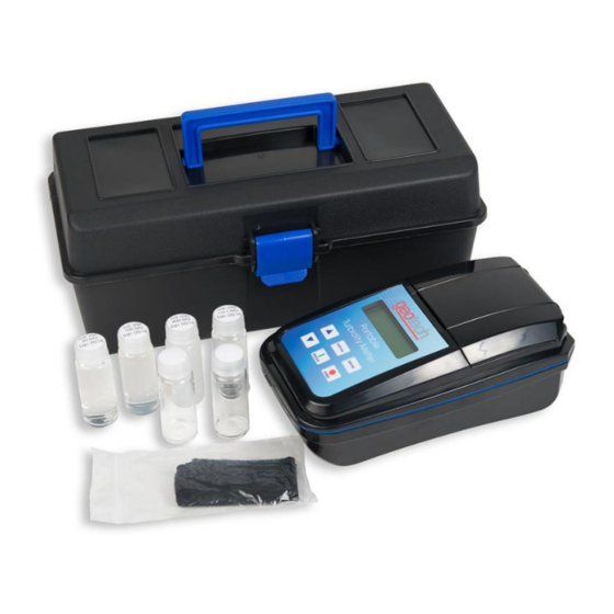
- Page 1 Portable Turbidity Meter Installation and Operation Manual Rev 3/12/2018 Part # 22100045...
-
Page 3: Table Of Contents
Table of Contents DOCUMENTATION CONVENTIONS ..............2 Section 1: System Description ................4 Function and Theory ..................4 Instrument Features ..................4 System Components ..................4 Section 2: System Installation & Navigation ........... 4 Install the battery ....................5 Sample Vial Handling ..................5 User Interface .................... -
Page 4: Documentation Conventions
DOCUMENTATION CONVENTIONS This uses the following conventions to present information: An exclamation point icon indicates a WARNING of a situation or condition that could lead to personal injury or death. You should not proceed until you read and thoroughly understand the WARNING message. - Page 5 In order to ensure your Turbidity Meter has a long service life and operates properly, adhere to the following cautions and read this manual before use. Disconnect from power source when not in use. Power input source must not exceed maximum ratings. ...
-
Page 6: Section 1: System Description
Section 1: System Description Function and Theory Geotech's Portable Turbidity Meter offers great precision, repeatability and ease of use in a low cost extremely robust portable/laboratory instrument. Data points from field sample events can be stored to memory and transferred to computer or other storage device. -
Page 7: Install The Battery
Section 2: System Installation & Navigation Install the battery With a small Phillips screwdriver, remove the battery cover (located on the backside of the instrument). Take care to keep the small screws and washers safe when removing the battery cover. Install four (4) AA alkaline or nickel metal hydride (NiMH) batteries. -
Page 8: User Interface
Figure 2-2: Sample chamber alignment User Interface Figure 2-3: Instrument Keypad DISPLAY Displays readings, diagnostics, and operational data. UP ARROW (▲) Scroll through menus, enter numbers and letters DOWN ARROW (▼) Scroll through menus, enter numbers and letters MENU Enters into main menu function, selects options to configure the instrument, select analysis, and moves cursor to the right. -
Page 9: Section 3: System Operation
Section 3: System Operation 3.1 Quick Start Guide To turn ON unit: press and hold the READ button for 3 seconds. To turn OFF unit: press and hold the ESC button for 3 seconds. Figure 3-1: Read (ON/Enter) ESC (OFF/Back) Basic Operation Turn instrument on by pressing READ for 3 seconds. -
Page 10: Menu Navigation
3.2 Menu Navigation The Geotech Portable Turbidity Meter has several configuration capabilities. The menu structure is easy and simple to operate, please follow the steps below to configure the unit according to your needs. To Enter Main Menu: With instrument turned on, press MENU key for 3 seconds to enter the Menu Function. - Page 11 User Use the ▲ or ▼ keys to set user number from 0-99. Use the READ or SAVE button to set the user number and exit to the ID menu. 3.2.2 Calibrate From the main menu, use the ▲ or ▼ keys select the Calibrate function, then press READ to enter that submenu.
- Page 12 On the “Cal. Auto” screen, there will be a value displayed from the previous calibration. Place one of the calibration standards into the sample chamber. Press READ button and wait for result. If necessary use ▲ or ▼ keys to change the displayed value for this standard to match its label, press and hold SAVE for 3 seconds.
- Page 13 3.2.3 Config (Configuration) From the main menu, use the ▲ or ▼ keys select the Config function, then press READ to enter that submenu. Time/Date When inside this configuration you can change Time and Date. Use MENU/READ to move the cursor right/left and ▲ or ▼ keys to adjust the numbers as desired.
- Page 14 or ▼ to select between the options and READ to enter it or ESC to go back to the previous menu. Auto off The Auto off function shall be activated to save the batteries; it can be configured to turn the unit off after 0 to 60 minutes of inactivity. Using ▲...
- Page 15 Measure Mode/ Fast Settling When selected, instrument will take a snapshot of the sample and display the immediate reading before particles settle in the vial (for high solids samples). Using ▲ or ▼ select yes or no, when done, press and hold SAVE for 3 seconds to store the data and ESC to return to the previous menu.
- Page 16 Edit To create sample names and their passwords: Choose the user number between 00 and 50, press READ Choose a name for this sample using ▲ to scroll faster to letters , ▼ to scroll faster to numbers (both can be used to go up or down) and MENU/READ (send the cursor to the right/left), press and hold SAVE for 3 seconds to store the data.
- Page 17 Tag Number Use ▲ or ▼ and MENU/READ (send the cursor to the right/left) to set an ID number for the unit, press and hold SAVE for 3 seconds to store the data. ID must be four (4) characters. Language Use ▲...
- Page 18 Serial Baud Sets the data rate in bits for data transmission. Options include: 57600, 38400, 19200, and 9600. Default/suggested configuration is 19200bits/sec. Press and hold SAVE for 3 seconds to store the data and ESC to return to the previous menu. Header Select Yes or No to display header.
- Page 19 and hold SAVE for 3 seconds to store the data. Password must be four (4) characters. Calibration Here you will assign a security level and password to access all the calibration functions. Using ▲ or ▼ select the desired security level, when done, press and hold SAVE for 3 seconds to store the data.
-
Page 20: Usb Connection
3.3 USB Connection 1. Plug the unit into the computer; wait for device driver to download. Device connection is successful if an additional COM port is recognized in the Device Manager. 2. Identify a communication port for the connection, look in the computer’s Device Manager (example: COM2, COM18). -
Page 21: Menu Structure
3.4 Menu Structure Use the “READ” button to enter into a sub menu, use the “ESC” button to exit a sub menu. -
Page 22: Section 4: System Maintenance
Section 4: System Maintenance The Geotech Portable Turbidity Meter is designed to be a low-maintenance lab instrument that can be used in the field. General cleaning guidelines: Use a soft cloth with mild soap and warm water to clean the unit. -
Page 23: Section 5: System Troubleshooting
Clean lenses inside sample chamber to ensure a clear read Clean outside of bottles Check the expiration date on the calibration standards. Expired standards will result in an inaccurate reading. If these troubleshooting guidelines have not resolved the problem, contact Geotech Environmental Equipment at 1-800-833-7958. -
Page 24: Section 6: System Specifications
Section 6: System Specifications Measurement Method Nephelometric EPA method 180.1 (GTW) Regulatory ISO method 7027 (GTI) EPA - White light Tungsten (GTW) Light Source ISO - 860nm LED (GTI) Range 0 to 1000 NTU (FNU) Accuracy ±2% of reading plus stray light ±1% of reading, or 0.01 NTU (FNU),... -
Page 25: Section 7: Parts And Accessories
CAL KIT, SECONDARY, TURBIDITY GEOTECH,GEL,0-10,0- *52100002 100,0-1000 52100007 CAL KIT,PRIMARY,IR,TURBIDITY,GEOTECH,.1,20,100,800NTU 22100046 VIAL,TURBIDITY,4PK 22100048 CLOTH,LINT FREE,TURBIDITY PPE041006 BATTERY, 1.5V, SIZE AA, EACH 22100045 MANUAL, PORTABLE TURBIDITY METER,GEOTECH *22100049 CASE,ECONOMY,TURBIDITY *52100004 COMM CABLE,USB,TURBIDITY *Indicates optional accessories. For additional information, please call Geotech Environmental Equipment at: 1-800-833-7958... - Page 26 Document Revisions EDCF # Description Rev/Date Release, SP 07/07/2016 Project Updated graphics, additional user instructions, StellaR, SP 06/08/2017 #1496 Project Added calibration kit part numbers, StellaR 9/28/2017 #1569 Project Added part number 82100004, 82100006, 52100007, and 3/12/2018 #1608 changed description for part number 82100003, 82100005, 52100000 –StellaR...
- Page 27 NOTES...
- Page 28 NOTES...
-
Page 29: Ec Declaration Of Conformity
EN 61000-6-3: 2012 EN 61326-1: 2013 EMC conformity established 5/24/2017 Production control follows the ISO 9001:2008 regulations and includes required safety routine tests. This declaration issued under the sole responsibility of Geotech Environmental Equipment, Inc. Joe Leonard Product Development Serial number... - Page 30 DOCUMENT REVISIONS EDCF# DESCRIPTION REV/DATE Release, SP 07/07/2016 Project Added Declaration of Conformity, general updates 05/26/2017 #1496 to images and menu descriptions, SB Updated parts list, updated menu navigation, Project#1496 6/15/2017 StellaR...
-
Page 31: The Warranty
Geotech agrees to repair or replace, at Geotech’s option, the portion proving defective, or at our option to refund the purchase price thereof. Geotech will have no warranty obligation if the product is subjected to abnormal operating conditions, accident, abuse, misuse, unauthorized modification, alteration, repair, or replacement of wear parts. - Page 32 Geotech Environmental Equipment, Inc. 2650 East 40th Avenue Denver, Colorado 80205 (303) 320-4764 ● (800) 833-7958 ● FAX (303) 322-7242 email: sales@geotechenv.com website: www.geotechenv.com...
Need help?
Do you have a question about the GTW and is the answer not in the manual?
Questions and answers