
Related Manuals for Fire-Lite UDACT-F


Summary of Contents for Fire-Lite UDACT-F
- Page 1 PN 50049:E0 ECN 01-106 Universal Digital Alarm Communicator/Transmitter UDACT-F Instruction Manual Document 50049 01/22/2001 Rev:...
- Page 2 While a fire alarm system may lower insurance Fire Alarm System Limitations rates, it is not a substitute for fire insurance! An automatic fire alarm system–typically made up of smoke Heat detectors do not sense particles of combustion and detectors, heat detectors, manual pull stations, audible warn- alarm only when heat on their sensors increases at a prede- ing devices, and a fire alarm control with remote notification termined rate or reaches a predetermined level.
- Page 3 Installation Precautions Adherence to the following will aid in problem-free installation with long-term reliability: WARNING - Several different sources of power can be con- Like all solid state electronic devices, this system may nected to the fire alarm control panel. Disconnect all sources operate erratically or can be damaged when subjected to light- of power before servicing.
- Page 4 This digital communicator has been designed to comply with standards set forth by the following regulatory agen- cies: • Underwriters Laboratories Standard UL 864 • NFPA 72 National Fire Alarm Code • CAN/ULC - S527M Standard for Control Units for Fire Alarm Systems Before proceeding, the installer should be familiar with the following documents.
-
Page 5: Table Of Contents
FIGURE 2-1: ABS-8RF........................14 2.2: Panel Mounting ............................14 2.2.1: MS-9200............................14 FIGURE 2-2: UDACT-F Mounting to MS-9200 ................14 FIGURE 2-3: External UDACT-F Mounting in ABS-8RF - MS-9200..........15 TABLE 2-1: Annunciator LED Assignments (MS-9200) ..............16 2.2.2: MS-9600............................17 FIGURE 2-4: UDACT-F Wiring to MS-9600..................17 TABLE 2-2: Annunciator LED Assignments (MS-9600) ..............18... - Page 6 CHAPTER 4: Operating Instructions ........................40 4.1: Normal Mode...............................40 4.1.1: Keypad Functions..........................40 4.1.2: Displays .............................41 FIGURE 4-1: UDACT-F Phone Connectors and LEDs ..............42 4.1.3: Normal Mode Operation ........................42 4.1.4: Key Report Descriptions ........................44 4.2: Type Mode ..............................44 4.2.1: Disabling of Zones or Points ......................45 4.2.2: Zone or Point Supervisory.........................45...
-
Page 7: Chapter 1: Product Description
FACP or may mount externally in a separate enclosure. EIA-485 annunciator com- munications bus and 24 volt (nominal) connections are required. The UDACT-F is capable of reporting 198 points or 56 zones when used with the MS-9200, 636 points or 99 zones when used with the MS-9600 and 56 zones when used with the Sensiscan 2000. - Page 8 Product Features UDACT-F Assembly FIGURE 1-1: Primary Phone Line Secondary Phone Line Modular Cables P/N MCBL-7 (order separately) Comm Fail Output (power-limited) 24 VDC power in (use power-limited 24 VDC source) (power-limited) EIA-485 connector (use power-limited source) Connect to J16 on MS-9200,...
-
Page 9: Controls And Indicators
• Primary Phone Line Active - red LED • Secondary Phone Line Active - red LED • TEST - green LED Compatible Panels The UDACT-F has been designed to be compatible with the following Fire•Lite control panels: • Sensiscan 2000 • MS-9200 • MS-9600 Digital Communicator Two modular phone jacks allow easy connection to telephone lines. -
Page 10: Circuits
, motor control circuits or SCR power circuits. Note: If the UDACT-F is installed in an MS-9200 FACP, the EIA-485 data line is supplied directly through UDACT-F connector J10 which connects via supplied ribbon cable to the MS-9200 main circuit board connector J16. -
Page 11: Telephone Requirements And Warnings
RENs, contact the telephone company to determine the maximum REN for the calling area. 1.7.2 Digital Communicator Before connecting the UDACT-F to the public switched telephone network, the installation of two RJ31X jacks is necessary. The following information if provided if required by the local telephone company: Manufacturer: Fire•Lite Alarms, Inc. -
Page 12: 4: For Canadian Applications
The termination of an interface may consist of any combination of devices subject only to the requirement that the sum of the REN of all devices does not exceed 5.” Representative: NOTIFIER/FIRE-LITE, CANADA 24 Viceroy Road Concord, Ontario L4K2L9 IC Certificate Number: 2132 6030 A Ringer Equivalence Number (REN): 0.6B... -
Page 13: Modes And Special Functions
Modes and Special Functions 1.8.1 Normal Mode Normal Mode is the standard mode of operation. In this mode, the UDACT-F monitors host FACP status as well as monitoring telephone line voltage. The UDACT-F reports system status information to UL listed Central Stations. -
Page 14: Chapter 2: Installation
Figure 2-2. Using the ribbon cable supplied with the UDACT-F, connect J10 on the UDACT-F to J16 on the MS-9200. Note that the colored edge of the ribbon cable must be oriented toward the top edge of the UDACT-F as illustrated in Figure 2-2. - Page 15 (earth ground) at fire alarm panel, or shield may be connected to TB1 Terminal 5 (shield) at UDACT-F as shown in Figure 2-3. Note that the shield end that is not connected should be insulated to prevent accidental grounding. Do not connect both ends of the shield under any circumstance, since a ground fault may result.
- Page 16 Panel Mounting CAUTION: Connecting a UDACT-F to an MS-9200 which also has an ACM, AFM or LDM Series annunciator con- nected, will alter the assignments of the first eight yellow LEDs on the annunciator as follows: Annunciator LED Assignments (MS-9200)
-
Page 17: 2: Ms-9600
(earth ground) at fire alarm panel, or shield may be connected to TB1 Terminal 5 (shield) at UDACT-F as shown in Figure 2-3. Note that the shield end that is not connected should be insulated to prevent accidental grounding. Do not connect both ends of the shield under any circumstance, since a ground fault may result. - Page 18 Panel Mounting Connecting a UDACT-F to an MS-9600 which also has an ACM, AFM or LDM Series annunciator connected, will not alter the assignments of the first eight yellow LEDs on the annunciator. Annunciator LED Assignments (MS-9600) TABLE 2-2: Assignment...
-
Page 19: 3: Sensiscan 2000
Connect the supplied Ground Strap from the UDACT-F Earth Ground terminal on TB3 to the CHS-4 chassis. Con- nect 24 VDC filtered, nonresettable power to TB1 Terminals 1 & 2 on the UDACT-F. Refer to Figure 2-7, “24 VDC Power Connection to UDACT-F,” on page 21. - Page 20 (P/N: 71244) across Terminals 3 (RS+) & 4 (RS-) if last or only device on EIA-485 line. Note that Terminals 6 (RS+) & 7 (RS-) are not used at this time. CPU-2000 UDACT-F Document #50049 Rev.E0 1/22/01 P/N 50049:E0...
- Page 21 Power (supervised and power-limited) TB1-2 - TB2-1 + - TB2-2 Cut jumper JP1 to make output nonresettable for use with UDACT-F UDACT-F MPS-24BF Note: Power for the UDACT-F must be 24 VDC filtered, nonresettable Document #50049 Rev. E0 01/22/01 P/N 50049:E0...
- Page 22 Panel Mounting CAUTION: Connecting a UDACT-F to a Sensiscan 2000, which also has an AFM or LDM series annunciator connected, will alter the assignments of the first eight yellow LEDs on the annunciator as follows: Sensiscan 2000 Annunciator LED Assignments...
-
Page 23: Ul Power-Limited Wiring Requirements
0.25" away from any nonpower-limited circuit wiring. Furthermore, all power-limited circuit wiring and nonpower-limited circuit wiring must enter and exit the cabinet through different knockouts and/or conduits. A typical wiring diagram for the UDACT-F is shown below. Typical Wiring Diagram for UL Power-limited Requirements... -
Page 24: Output Circuits
PH2 (Secondary). Telephone line control/command is possible via double line seizure as well as usage of an RJ31X style interconnection. The RJ31X jacks must be ordered separately. Note that it is critical that the UDACT-F be located as the first device on the incoming telephone circuit to properly function. -
Page 25: 2: Relay Driver
Wiring from the UDACT-F terminal block TB3 to the relay must be in the same room no more than 20 feet (6 m) in length and enclosed in conduit. Wiring from the relay output contacts must also remain in the same room as the UDACT-F. - Page 26 (MR-201/C may also be used) Note: MMF-300 Series Monitor Module is used to supervise Normally Closed output of MR-101/C. On UDACT-F trouble and Comm. Fail, MR-101/ C relay contact will open, causing M300 to transmit trouble condition to the FACP .
-
Page 27: Chapter 3: Programming Instructions
56 is changed to 1, 2, 3, 4, 5 or 6. Refer to program selection for address 56 in this section. Once location 56 is changed from 0 to 1, 2, 3, 4, 5 or 6 and a valid phone number is entered, transmission of the 'UDACT-F Off Nor- mal' report will occur. -
Page 28: Switch (Key) Functions
Switch (Key) Functions Switch (Key) Functions The function of each switch (key) in Program Mode is illustrated in Figure 3-1. UDACT-F Keypad FIGURE 3-1: No function in Program Mode Select operating mode Increment memory address Address entry keys are 0 to 9... - Page 29 F: Not used Note: Consult the Central Station for proper selection or consult the factory representatives. For any format chosen, the UDACT-F automatically programs all of the event codes. Refer to Table 3-2 on page 34, Table 3-3 on page 35, Table 3-4 on page 36, Table 3-5 on page 37, Table 3-6 on page 38 and Table 3-7 on page 39.
- Page 30 F: Not used Note: Consult the Central Station for proper selection or consult the factory representatives. For any format chosen, the UDACT-F automatically programs all of the event codes. Refer to Table 3-2 on page 34, Table 3-3 on page 35, Table 3-4 on page 36, Table 3-5 on page 37, Table 3-6 on page 38 and Table 3-7 on page 39.
- Page 31 3 = Report status of 56 zones Note: For additional information on the starting and ending addresses, refer to the host FACP Technical Manual. UDACT-F Communication Selection (56) Leaving address 56 at '0' disables communications to the Central Station(s). Enter '1' for zone reporting receive only,...
- Page 32 F = 23 hours 8 = 16 hours Host Panel ID (63) Enter one of the following digits corresponding to the control panel in which the UDACT-F is installed. A correct entry is essential for proper operation. 0 = MS-9200...
- Page 33 Exit Programming Mode by pressing the MODE key, followed by the 4-digit code corresponding to an alternate mode of operation, then press the [ENTER/STORE] key. During Program Mode, if no key is pressed within 10 min- utes, the UDACT-F will revert to Normal Mode. Document #50049 Rev.
- Page 34 Primary # Communication Trouble Secondary Number Restore Code Primary # 485 Communication Trouble Restore Code Primary # System Off Normal Restore Code Primary # UDACT-F Off Normal Restore Code Primary # System 24 Hour Test Primary # System 24 Hour Test with Active Event...
- Page 35 Primary # 485 Communication Trouble Restore Code 129 - 130 Primary # System Off Normal Restore Code 131 - 132 Primary # UDACT-F Off Normal Restore Code 133 - 134 Primary # System 24 Hour Test 135 - 136 Primary # System 24 Hour Test with Active Event...
- Page 36 Refer to Contact ID program locations 64 - 68 The identification of the zone/sensor number is automatically transmitted by the UDACT-F and is added to the main event code. Refer to Table A-3, “Ademco Contact ID Reporting Structure,” on page 49, for additional...
- Page 37 Secondary # Communication Trouble Secondary Number Restore Code Secondary # 485 Communication Trouble Restore Code Secondary # System Off Normal Restore Code Secondary # UDACT-F Off Normal Restore Code Secondary # System 24 Hour Test Secondary # System 24 Hour Test with Active Event...
- Page 38 Secondary # 485 Communication Trouble Restore Code 199 - 200 Secondary # System Off Normal Restore Code 201 - 202 Secondary # UDACT-F Off Normal Restore Code 203 - 204 Secondary # System 24 Hour Test 205 - 206 Secondary # System 24 Hour Test with Active Event...
- Page 39 Refer to Contact ID program locations 64 - 68 The identification of the zone/sensor number is automatically transmitted by the UDACT-F and is added to the main event code. Refer to Table A-3, “Ademco Contact ID Reporting Structure,” on page 49, for additional...
-
Page 40: Chapter 4: Operating Instructions
Test If the TEST key is pressed three times in rapid succession, the UDACT-F will transmit a test message to both Central Stations. The message reported is the same as the automatic test message for all formats except Ademco Contact ID. -
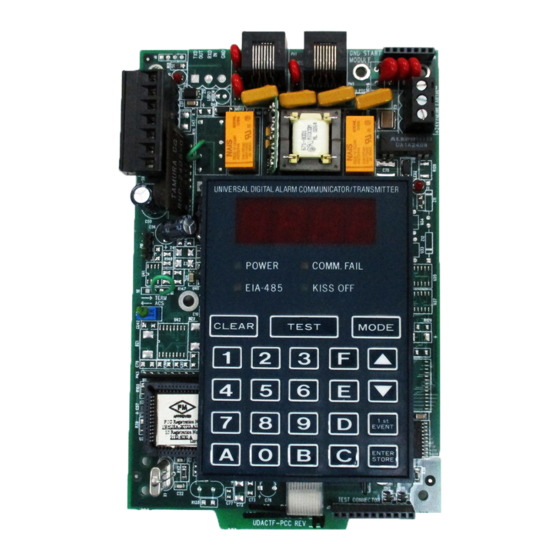
Page 41: 2: Displays
Central Stations had been unsuccessful. During a comm. fail, the display will show either a PH1 and PH2 or no1 and no2. Power On A green LED that remains on while DC power is supplied to the UDACT-F. If this indicator fails to light under nor- mal conditions, service the system immediately. Kissoff A green LED that blinks when the Central Station has acknowledged receipt of each transmitted message. -
Page 42: 3: Normal Mode Operation
The UDACT-F comes with line seizure capability provided for both the primary and secondary telephone line inter- faces. Any time that the UDACT-F needs to make a call to the Central Station, line seizure will disconnect any local premises phones sharing the same telephone line. - Page 43 Normal Mode Since higher priority events take precedence over lower priority events, the UDACT-F will transmit higher priority events before sending the lower priority events. Priorities are as follows: Event Activations General Alarm Zone/Point Alarm #N General Supervisory Zone/Point Supervisory #N...
-
Page 44: 4: Key Report Descriptions
Type Mode The UDACT-F is supplied factory programmed with the reports identified above as item numbers 2, 4, 7, 20, 22 and 25 set to zero, preventing the reports from being transmitted for the pulsed and Ademco Express formats. These reports are factory programmed for active transmission when using the Ademco Contact ID. -
Page 45: 1: Disabling Of Zones Or Points
4.2.2 Zone or Point Supervisory A zone or point must be defined as supervisory to allow the UDACT-F to identify the correct report to transmit to the Central Station. Follow the programming instructions in the FACP manual to program a zone or point as supervisory. -
Page 46: Troubleshoot Mode
To perform a Lamp Test, press the MODE key and then enter the code 5267. Next, press the [ENTER/STORE] key to test all system LEDs. The LEDs will stay on for five seconds, then the UDACT-F will return to Normal Mode. -
Page 47: Appendix A: Reporting Formats
Reporting Formats Reporting Formats Appendix A Table A-1 shows the data reporting structure for each of the pulsed formats as well as the Ademco Express formats. Ademco Express formats allow a typical data message to be transmitted to the Central Station in under five seconds. Pulsed formats typically require 15 to 20 seconds in comparison. - Page 48 Reporting Formats Letter Code Definitions for Table A-1 TABLE A-2: Where: SSS or SSSS Subscriber ID Alarm (1st digit) Alarm (2nd digit) Alarm Restore (1st digit) Alarm Restore (2nd digit) Zone Trouble (1st digit) Zone Trouble (2nd digit) Zone Trouble Restore (1st digit) RTZ2 Zone Trouble Restore (2nd digit) System Trouble (1st digit)
- Page 49 Reporting Formats The reporting structure for the Ademco Contact ID format is as follows: Ademco Contact ID Reporting Structure TABLE A-3: SSSS 18 QXYZ GG CCC where SSSS Four digit Subscriber ID (addresses 17 - 20 and 43 - 46) Identifies transmission of Contact ID to the receiver at the Central Station Event Qualifier E = New Event...
- Page 50 Reporting Formats Point Reporting By using the Type Mode feature with address 56 set to 3, 4, 5 or 6, identification of each type of activated device is possible. Note that addressable detectors report as code 111. It should also be noted that the meaning of the first digit of the three digit zone/sensor number will depend on the Type Mode programmed in address 56 (i.e.
-
Page 51: Appendix B: Compatible Receivers
Compatible Receivers Compatible Receivers Appendix B The chart below shows UL listed receivers compatible with the UDACT-F. Compatible UL Listed Receivers TABLE B-1: Format # (Addresses 16 & 42) ✔ ✔ ✔ 4+1 Ademco Express ✔ ✔ ✔ ✔ 4+2 Ademco Express ✔... -
Page 52: Appendix C: Programming Reference Sheets
End Monitoring Address. ❐ UDACT-F Communication Selection. Enter '0' to disable UDACT-F communication; '1' for zone reporting receive only communication; '2' for zone reporting receive/transmit communication; '3' for point reporting receive only communication; '4' for point reporting receive/transmit communication; '5' for code wheel matching reporting, receive only;... - Page 53 Programming Reference Sheets Programming Reference Sheets ❐ ❐ ❐ ❐ ❐ ❐ ❐ ❐ ❐ ❐ ❐ ❐ ❐ ❐ ❐ ❐ ❐ ❐ ❐ ❐ ❐ ❐ ❐ ❐ ❐ ❐ ❐ ❐ ❐ ❐ ❐ ❐ ❐ ❐ ❐...
- Page 54 ❐ Start Monitoring Address. ❐ ❐ End Monitoring Address. ❐ UDACT-F Communication Selection. '0' to disable UDACT-F communication. ❐ Backup Reporting. '0' to have secondary phone number act as backup only. ❐ Touchtone/Rotary Select. '0' for touchtone dialing. ❐ Make/Break Ratio. '0' for a 67/73 make/break ratio.
- Page 55 Programming Reference Sheets Programming Reference Sheet Factory Default ❐ ❐ ❐ ❐ ❐ ❐ ❐ ❐ ❐ ❐ ❐ ❐ ❐ ❐ ❐ ❐ ❐ ❐ ❐ ❐ ❐ ❐ ❐ ❐ ❐ ❐ ❐ ❐ ❐ ❐ ❐ ❐ ❐...
-
Page 56: Appendix D: Point Assignments - Ms-9200
Point Assignments - MS-9200 Point Assignments - MS-9200 Appendix D (Program Address 56 = 3 or 4) Use chart to carefully identify all points in the system. Leading zero (0) in point number signifies detectors and lead- ing one (1) signifies modules. Take special precaution with any supervisory points and remote switches in the system. Use Type Mode to match the function of remaining points in the system for proper reporting (see "Type Mode"... -
Page 57: Appendix E: Code Wheel Matching Point Assignments - Ms-9200
Code Wheel Matching Point Assignments - MS-9200 Code Wheel Matching Point Assignments - Appendix E MS-9200 (Program Address 56 = 5 or 6) Use chart to carefully identify all points in the system. Take special precaution with any supervisory points and remote switches in the system. -
Page 58: Appendix F: Point Assignments - Ms-9600
Point Assignments - MS-9600 Point Assignments - MS-9600 Appendix F (Program Address 56 = 3 or 4) Type Mode Programming To disable or identify a zone or point in Type Mode (refer to “Type Mode” on page 44), the following Entries/ Addresses are used: F.1.1 For Zone Identification: Zones 1 - 99 are programmed by Entries/Addresses 01 - 99. -
Page 59: F.3: Point Assignments
Point Assignments - MS-9600 Point Assignments Use chart to carefully identify all points in the system. Take special precaution with any supervisory or non-fire points and remote switches in the system. Use Type Mode to match the function of remaining points in the system for proper reporting (see "Type Mode"... - Page 60 Point Assignments - MS-9600 Point Assignments continued: Type of Device: Type of Device: Type of Device: Type of Device: Point Module Loop 1 Point Module Loop 1 Point Module Loop 2 Point Module Loop 2 Continued on the next page... Document #50049 Rev.E0 1/22/01...
- Page 61 Point Assignments - MS-9600 Point Assignments continued: Type of Device: Type of Device: Type of Device: Type of Device: Point Module Loop 1 Point Module Loop 2 Point Detector Loop1 Point Detector Loop 1 Not Used Not Used Note: Addressable detectors on Loops 1 and 2 may be disabled using Type Mode. The Event Code cannot be altered. Continued on the next page...
- Page 62 Point Assignments - MS-9600 Point Assignments continued: Type of Device: Type of Device: Type of Device: Type of Device: Point Detector Loop 2 Point Detector Loop 2 Point Detector Loop1 Point Detector Loop 1 Note: Addressable detectors on Loops 1 and 2 may be disabled using Type Mode. The Event Code cannot be altered. Continued on the next page...
- Page 63 Point Assignments - MS-9600 Point Assignments continued: Point Type of Device: Point Type of Device: Point Type of Device: Point Type of Device: Detector Loop 2 Detector Loop 2 Detector Loop1 Detector Loop 2 Not Used Not Used Note: Addressable detectors on Loops 1 and 2 may be disabled using Type Mode. The Event Code cannot be altered. Document #50049 Rev.
-
Page 64: Appendix G: Zone Assignments
Zone Assignments Zone Assignments Appendix G Use chart to carefully identify all zones in the system. Take special precaution with any supervisory or non-fire zones in the system. Use Type Mode to match the function of remaining points in the system for proper reporting (see "Type Mode"... - Page 65 Document #50049 Rev. E0 01/22/01 P/N 50049:E0...
- Page 66 Document #50049 Rev.E0 1/22/01 P/N 50049:E0...
- Page 67 Limited Warranty The manufacturer warrants its products to be free from defects in materials and workmanship for eighteen (18) months from the date of manufacture, under normal use and service. Products are date-stamped at time of manufacture. The sole and exclusive obligation of the manufacturer is to repair or replace, at its option, free of charge for parts and labor, any part which is defective in materials or workmanship under normal use and service.
- Page 68 World Headquarters One Fire-Lite Place, Northford, CT 06472-1653 USA 203-484-7161 • Fax 203-484-7118 www.firelite.com...
Need help?
Do you have a question about the UDACT-F and is the answer not in the manual?
Questions and answers