
Related Manuals for Fire-Lite 411UD


Summary of Contents for Fire-Lite 411UD
- Page 1 Digital Alarm Communicator/Transmitters 411/411UD Manual Document LS10105-000GE-E 1/29/2014 Rev: P/N LS10105-000GE-E:A ECN 13-875...
- Page 2 Adequate written records of all inspections should be kept. (especially in bedrooms), smoking in bed, and violent explosions Limit-D-1-2013 411 & 411UD Manual — P/N LS10105-000GE-E:A 1/29/2014...
-
Page 3: Installation Precautions
LonWorks™ is a trademark of Echelon Corporation. ARCNET® is a registered trademark of Datapoint Corporation. Microsoft® and Windows® are registered trademarks of the Microsoft Corporation. ©2014. All rights reserved. Unauthorized use of this document is strictly prohibited. 411 & 411UD Manual — P/N LS10105-000GE-E:A 1/29/2014... - Page 4 •Your suggestion for how to correct/improve documentation Send email messages to: FireSystems.TechPubs@honeywell.com Please note this email address is for documentation feedback only. If you have any technical issues, please contact Technical Services. 411 & 411UD Manual — P/N LS10105-000GE-E:A 1/29/2014...
-
Page 5: Table Of Contents
1.2: Specifications...............................10 Operating Power...........................10 DC Power - TB1 Terminals 4(+) and 5(-), Terminal 6 is Earth Ground..........10 Channels/Inputs - TB2 Terminals 1 through 6 (411) or 8 (411UD).............11 One Form-C Relay - TB1 Terminals 1 through 3 ................11 1.3: Circuits.................................11 1.3.1: Power Requirements..........................11... - Page 6 Future Use (91 - 93)..........................38 Service Terminal 1 Phone Number (94 - 113) - 411UD Only..............38 Ring Count on Primary Phone Line (114 - 115) - 411UD Only............38 Future Use (116) ...........................38 Service Terminal 2 Phone Number (117 - 136) - 411UD Only............38 Upload/Download Reports Sent to Secondary Central Station Phone #, Backup or Always (137) - 411UD Only............................38...
- Page 7 Table of Contents Section 5: Remote Site Upload/Download - 411UD Only ............ 47 5.1: General.................................47 5.1.1: Security Features ..........................48 Secret Code Verification ........................48 Panel Unlock ............................48 Time-out at 411UD..........................49 Callback to Service Terminal .......................49 Error Checking .............................49 Central Station Acknowledge.......................49 Data Protection/Integrity ........................49...
- Page 8 UL 864, 9th Edition. Operation of this product with products not tested for UL 864, 9th Edition has not been evaluated. Such operation requires the approval of the local Authority Having Jurisdiction (AHJ). 411 & 411UD Manual — P/N LS10105-000GE-E:A 1/29/2014...
-
Page 9: Section 1: Product Description
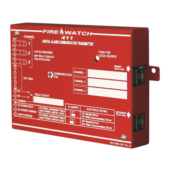
Section 1: Product Description The 411 is a three, and the 411UD is a four input/channel, dual line, digital communicator which can be used as a slave communicator with UL listed fire and non-fire control panels. The three or four inputs are compatible with normally open relay contacts, require End-Of-Line (EOL) resistors, and are fully programmable. -
Page 10: Specifications
12 or 24 VDC power. The configuration of Jumper J4 determines whether 12 VDC power is to be supplied directly to the 411/411UD circuit board or 24 VDC power is to be supplied and then internally regulated down internally to 12 VDC. -
Page 11: Channels/Inputs - Tb2 Terminals 1 Through 6 (411) Or 8 (411Ud)
Figure 1.3 J4 Jumper Selection 1.3.2 Channels/Inputs Three (411) or four (411UD) input channels are provided on the 411/411UD digital communicator which are used for connection to the control panel being monitored. Each input can be pro- grammed to monitor the control panel for: •... -
Page 12: 3: Primary And Secondary Phone Lines
Connect a separate earth ground wire to TB1 terminal 6 for transient protection. 1.4 Controls and Indicators Comm. Fail LED Piezo Silence Switch PH1 LED Comm. Fail LED PH2 LED J4 Jumper- voltage select Figure 1.4 411 Controls and Indicators 411 & 411UD Manual — P/N LS10105-000GE-E:A 1/29/2014... -
Page 13: Front Panel Switch
Silence Switch - press to silence local 411/411UD piezo sounder Piezo Sounder The 411/411UD piezo sounder is used to locally annunciate DACT troubles. DACT troubles include input channel open circuit, phone line 1 or 2 voltage fault, phone number 1 or 2 communi- cation fault, total communication failure and communications disabled. -
Page 14: Digital Communicator Operation
Digital Communicator Operation 1.5 Digital Communicator Operation The 411/411UD has been designed to be compatible with a wide variety of fire alarm, non-fire and combination control panels. Numerous formats are also available for communication to a central station. Two modular phone jacks allow easy connection to telephone lines. Modular jacks are labeled PH1 and PH2 for the Primary and Secondary phone lines. -
Page 15: 3: Telephone Company Rights And Warnings
While the communicator is in Troubleshoot Mode, it does not monitor channel inputs. 1.7.5 Default Mode Default Mode may be used to return all 411/411UD programming back to the factory default set- tings. 411 & 411UD Manual — P/N LS10105-000GE-E:A 1/29/2014... -
Page 16: Section 2: Installation
12VDC or 24VDC nominal power connections are made to TB1 on the 411/411UD circuit board. When jumper J4 is shorted across pins 1 and 2, the 411/411UD is set for 12 VDC nominal operating voltage. Power-limited, filtered, nonresettable 12 VDC nominal operating power can be supplied directly to the 411/411UD by a UL listed 12 VDC power supply listed for fire protection or by a nonresettable 12 VDC output from a control panel. -
Page 17: Input Channels
AC Loss Reporting - 411UD: Channel 4 which is defaulted to AC Loss on the 411UD, or any chan- nel programmed for AC Loss, will transmit a specific AC loss signal only if the assigned Normally Open contact provides this function. -
Page 18: Channel Labels
2.4 Output Circuits Relays The 411/411UD provides one Form-C relay rated for 2.0 amps @ 30 VDC (resistive). The relay is programmable for activation on fire alarm, host panel trouble, fire supervisory, total communica- tion failure, AC loss and DACT trouble. -
Page 19: Telephone Circuits
RJ31X style interconnection. (RJ31X jacks must be ordered sepa- rately). CAUTION: It is critical that the 411/411UD be located as the first device on the incoming tele- phone circuit to properly function. (Secondary Lines) Incoming... -
Page 20: Optional Programmer
Note that it is not possible to switch from Normal Mode to any other mode if any of the 3 (411) or 4 (411UD) Channels is programmed for fire alarm or fire supervisory, and is active, that is, in alarm (shorted). -
Page 21: Ul Power-Limited Wiring Requirements
Installation 2.7 UL Power-limited Wiring Requirements The three (411) or four (411UD) input channels are power-limited circuits. Power supplied to the 411/411UD must be power-limited 12 or 24 volts, filtered and nonresettable. The relay circuit must be connected to power-limited circuits. Do not connect nonpower-limited wiring to any circuits on the 411/411UD. -
Page 22: Section 3: Modes Of Operation
Both telephone lines are supervised by the 411/411UD for proper voltage. The 411/411UD is capable of line seizure on both the primary and secondary telephone line inter- faces. Any time the digital communicator detects the necessity to call the Central Station, line sei- zure will disconnect any local premises phones sharing the same telephone line. -
Page 23: 1: Programmer Key Functions
If an incorrect key is entered, reenter the proper 4-digit code before pressing the [ENTER/STORE] key. Note that as information is entered into the 411/411UD, the digits will scroll across the Pro- grammer display from right to left. ___6... -
Page 24: 1St Event Key
Use the UP arrow key to increment the memory address and view its content. [ENTER/STORE] Stores entry into nonvolatile E memory located on the 411/411UD printed circuit board, then increments to the next higher address. 3.1.2 Programmer Display Four 7-segment red LED characters provide visual display of information in the various modes of operation. -
Page 25: Real Time Clock Mode
If an incorrect key is entered, reenter the proper 4-digit code before pressing the [ENTER/STORE] key. Note that as information is entered into the 411/411UD, the digits will scroll across the Pro- grammer display from right to left. ___2... - Page 26 Note that upon power-up, the internal clock starts running at 00:00 midnight. It must be changed so that the 411/411UD can accurately call in test signals to the Central Station. Upon power loss, the clock reverts to 00:00 midnight and must be reset.
-
Page 27: Program Mode
If an incorrect key is entered, reenter the proper 4-digit code before pressing the [ENTER/STORE] key. Note that as information is entered into the 411/411UD, the digits will scroll across the Pro- grammer display from right to left. ___7... -
Page 28: 1: Dact Programming
The Programmer cable should not be removed from the 411/411UD unless the communicator is in Normal Mode. If the Programmer cable is removed while the 411/411UD is in a Mode other than Normal Mode, the communicator will automatically revert to Normal Mode following a 10 minute time-out period. -
Page 29: Primary Central Station Number Communication Format (20)
20. The addresses shown in each Table contain the Setting data which is auto- matically programmed by the 411/411UD. To change the value, key in the new digit and then press the [ENTER/STORE] key to save the new value. Use the Up and Down Arrow keys to increment to the next address or decrement to the previous address. -
Page 30: Ademco Contact Id Format Primary Central Station Event Codes
Primary # Input Channel 2 Active Event Code 144 - 146 Primary # Input Channel 3 Active Event Code 147 - 149 Primary # Input Channel 4 Active Event Code - 411UD Only 150 - 152 Primary # Input Channel 1 Fault Event Code 153 - 155... -
Page 31: All 3+1, 4+1 And 4+2 Expanded Formats Primary Central Station Event Codes
Primary # Input Channel 2 Active Event Code Primary # Input Channel 3 Active Event Code Primary # Input Channel 4 Active Event Code - 411UD Only Primary # Input Channel 1 Fault Event Code Primary # Input Channel 2 Fault Event Code... -
Page 32: Primary Central Station Number 24/12/8/6 Hour Test Time Interval (29)
1: 4+2 Ademco Express Standard, DTMF, 1400/2300 ACK 2: 3+1 Standard 1800 Hz Carrier, 2300 Hz ACK 3: 3+1 Expanded 1800 Hz Carrier, 2300 Hz ACK 4: 3+1 Standard 1900 Hz Carrier, 1400 Hz ACK 411 & 411UD Manual — P/N LS10105-000GE-E:A 1/29/2014... -
Page 33: Ademco Contact Id Format Secondary Central Station Event Codes
50. The addresses shown in each Table contain the event code Setting data which is automatically programmed by the 411/411UD. To change the value, key in the new digits and then press the [ENTER/STORE] key to save the new value. Use the Up and Down Arrow keys to increment to the next address or decrement to the previous address. -
Page 34: Standard And 4+2 Express Formats Secondary Central Station Event Codes
Secondary # Input Channel 2 Active Event Code 206 - 207 Secondary # Input Channel 3 Active Event Code 208 - 209 Secondary # Input Channel 4 Active Event Code - 411UD Only 210 - 211 Secondary # Input Channel 1 Fault Event Code 212 - 213... -
Page 35: All 3+1, 4+1 And 4+2 Expanded Formats Secondary Central Station Event Codes
Secondary # Input Channel 2 Active Event Code Secondary # Input Channel 3 Active Event Code Secondary # Input Channel 4 Active Event Code - 411UD Only Secondary # Input Channel 1 Fault Event Code Secondary # Input Channel 2 Fault Event Code... -
Page 36: Secondary Central Station Number 24/12/8/6 Hour Test Time Interval (59)
Central Station(s). An entry of '1' in this location enables communication to the Central Station(s). Note that upon power-up, the 411/411UD will immediately annunciate a DACT trouble since the communicator is factory defaulted to 'communicator disabled' at program location 64. -
Page 37: Input Channel 3 Function Selection (67)
Factory default for Channel 4 is '4' for activation on AC Loss. Enter '0' for Fire Alarm; '1' for Host Control Panel Trouble; '2' for Fire Supervisory. Note that the AC Loss function requires a Nor- mally Open contact dedicated to AC loss function. The 411UD transmits a specific AC Loss event code if desired. -
Page 38: Panel Unlock (90)
Addresses 94 - 113 are reserved for the Service Terminal Number 1 phone number. Factory default is all 'F's. Valid entries are 0 - 9 plus A, B, C, D, and E. Use 'F' to designate the end of the phone number. See Section 5, “Remote Site Upload/Download - 411UD Only” for additional informa- tion. -
Page 39: Default Mode
® phone. Once in this mode, the 411/411UD will continue to communicate any events not yet acknowledged at a central station prior to entering Troubleshoot Mode. The UP arrow, DOWN arrow, and 1st EVENT keys do not function in this mode. - Page 40 Figure 3.2. The handset, when connected across T1, may be used only as an amplifier/speaker or telephone with the keypad used for number dialing. Both Primary and Secondary Lines Figure 3.2 Handset/Speaker Connection 411 & 411UD Manual — P/N LS10105-000GE-E:A 1/29/2014...
-
Page 41: Section 4: Central Station Communications
DACT Trouble LED will turn on (411UD Only), the trouble relay will activate if programmed for DACT trouble and the trouble con- dition will be reported to a central station over the remaining good phone line. - Page 42 Test Report SSS(S) X SSS(S) X SSSS XX2 SSSS XX2 Up or Download - 411UD Only SSS(S) UD SSS(S) UD SSS UDUD2 SSS UDUD2 Table 4.1 Format Selection Addresses (20 and 50) Programming 411 & 411UD Manual — P/N LS10105-000GE-E:A 1/29/2014...
- Page 43 Note that for Expanded Reporting, the digital communicator automatically adds the digit corre- sponding to the Channel/Input number, and the second digit corresponding to any system trouble condition. Only the first digit shown in Table 3.3 and Table 3.6 is programmable. 411 & 411UD Manual — P/N LS10105-000GE-E:A 1/29/2014...
-
Page 44: Transmittal Priorities
System Off Normal System Test Upload/Download events (lowest priority) - 411UD Only Red LEDs are provided on the digital communicator circuit board (411UD Only) to identify which telephone line is active. 4.2 Ademco Contact ID Format Event Code Description This section describes the various Event Codes and their messages which are available for the Ademco Contact ID Format. -
Page 45: Ademco Contact Id Reporting Structure
03/25 7777 R380 C003 - Channel/Input 3 fault restored 11:28 03/25 7777 E158 C004 - high temperature, Channel/Input 4 - 411UD Only 11:28 03/25 7777 E151 C004 - gas detected, Channel/Input 4 - 411UD Only 411 & 411UD Manual — P/N LS10105-000GE-E:A 1/29/2014... - Page 46 Central Station Communications Ademco Contact ID Format Event Code Description The following table contains UL listed receivers compatible with the 411/411UD digital communi- cator. Format # (Addresses 20 and 50) 4+1 Ademco Express ...
-
Page 47: Section 5: Remote Site Upload/Download - 411Ud Only
Section 5: Remote Site Upload/Download - 411UD Only The 411UD digital communicator may be programmed off site via the public switched telephone network. Any personal computer with Windows ® XP or greater, with a 1200 Baud Hayes compati- ble modem and Upload/Download software P/N PK-411UD (available online or on the PK-CD programming CD) may serve as a Service Terminal. -
Page 48: 1: Security Features
Central Station(s). 5.1.1 Security Features Remote site upload and download with the 411UD have been carefully designed to include key security features to ensure proper functionality. The key features are listed and explained below. Secret Code Verification A secret code is stored in the communicator by a Service Terminal to prevent unauthorized access. -
Page 49: Time-Out At 411Ud
• uploading/downloading was not successful Data Protection/Integrity Programming data is completely verified for accuracy prior to reprogramming of the 411/411UD EEPROM. Incomplete or corrupted data packets are ignored or retried. 5.2 Downloading to the Communicator Before initiating the download procedure, make certain that the communicator is in the standby state;... -
Page 50: Uploading From The Communicator
communicator must be in a standby state with no new information waiting to be transmitted to a Central Station. Once an incoming call is accepted/answered by the communicator, the 411UD will: Establish basic modem connection Verify secret code Verify callback vs. no callback request from the Service Terminal. If callback is requested, perform steps 4 through 10;... -
Page 51: Appendix A: Programming Sheets
Communicator Enable/Disable. Enter '0' to disable communication to Central Station; '1' to enable. Default entry of '0' causes the 411/411UD to annunciate a DACT trouble immediately on power-up. Input Channel 1 Function Selection. Enter '0' for fire alarm; '1' for host control panel trouble; '2' for fire super- visory;... - Page 52 - 411UD Only Ring Count on Primary Phone Line. Enter number of rings prior to panel answering call. Valid entries are 00 to 25 (00 = no answer). Factory default is 03. - 411UD Only Future Use. ...
-
Page 53: A.2: Digital Communicator Options Program Sheet (Factory Defaults)
Input Channel 2 Function Selection. '1' for host control panel trouble. Input Channel 3 Function Selection. '2' for fire supervisory. Input Channel 4 Function Selection. '4' for AC loss - 411UD Only. Future Use ... - Page 54 Addresses 94 to 113 store the Service Terminal 1 Phone Number. Valid entries are 0 - 9 and A - E. 'F' designates the end of the phone number - 411UD Only. Ring Count on Primary Phone Line. '03' for number of rings before answering call - 411UD Only. Future Use. ...
-
Page 55: Appendix B: Event Codes/Transmission Format Programming Sheets
411 & 411UD Manual — P/N LS10105-000GE-E:A 1/29/2014... -
Page 56: B.3: 4+2 Standard & 4+2 Express Formats Primary Central Station
411 & 411UD Manual — P/N LS10105-000GE-E:A 1/29/2014... -
Page 57: B.5: All 3+1, All 4+1 And 4+2 Expanded Formats For Primary Central Station
411 & 411UD Manual — P/N LS10105-000GE-E:A 1/29/2014... -
Page 58: B.9: Ademco Contact Id Format Primary Central Station
411 & 411UD Manual — P/N LS10105-000GE-E:A 1/29/2014... -
Page 59: Appendix C: Ademco Contact Id Format Event Code Description
132 Interior BURG - Interior - # 133 24-Hour BURG - 24-Hour 134 Entry/Exit BURG - Entry/Exit - # 135 Day/Night BURG - Day/Night - # 136 Outdoor BURG - Outdoor - # 411 & 411UD Manual — P/N LS10105-000GE-E:A 1/29/2014... - Page 60 Sounder/Relay Troubles - 320 320 Sounder/Relay TROUBLE - Sounder/Relay - # 321 Bell 1 TROUBLE - Bell/Siren #1 322 Bell 2 TROUBLE - Bell/Siren #2 323 Alarm relay TROUBLE - Alarm Relay 411 & 411UD Manual — P/N LS10105-000GE-E:A 1/29/2014...
- Page 61 OPENING - Keyswitch CLOSING - Keyswitch Remote Access - 410 411 Callback request made REMOTE - Callback Requested Restore not applicable 412 Success - download/access REMOTE - Successful Access Restore not applicable 411 & 411UD Manual — P/N LS10105-000GE-E:A 1/29/2014...
- Page 62 Restore not applicable 606 Listen-in to follow LISTEN - Listen-in Active Restore not applicable 607 Walk test mode TEST - Walk Test Mode 608 System abnormal test TEST - System Abnormal Test 411 & 411UD Manual — P/N LS10105-000GE-E:A 1/29/2014...
-
Page 63: Appendix D: Wire Requirements
Appendix D: Wire Requirements It is important to use the correct type of wire, wire gauge and wire run length per each 411/411UD circuit. Reference the following table to specify wire requirements and limitations for each digital communicator. CIRCUIT CONNECTIONS... -
Page 64: Appendix E: Operational Modes
Returns digital communicator to factory Fire protection is off during Default Mode. default program settings 8768 (TROU) Allows testing of both telephone lines Fire protection is off during Troubleshoot Mode. Table E.1 Operational Modes 411 & 411UD Manual — P/N LS10105-000GE-E:A 1/29/2014... -
Page 65: Index
Digital Alarm Communicator Transmitter 9 Modes of Operation 15 Data Protection/Integrity 49 Mounting 16 Default Mode 15 Description 9 Dialer Runaway 10 Digital Alarm Communicator Transmitter Normal Mode 15 see DACT Downloading 49 411 & 411UD Manual — P/N LS10105-000GE-E:A 1/29/2014... - Page 66 Label 18 Programmable 10 Programming 18 see Ringer Equivalence Number Ringer Equivalence Number 14 RJ31X 19 see Phone Connector - Male Secret Code see Service Terminal Secret Code Verification 48 Security Features 411 & 411UD Manual — P/N LS10105-000GE-E:A 1/29/2014...
- Page 67 Manufacturer's Return Material Authorization form. The replacement part shall come from Manufacturer's stock and may be new or refurbished. THE FOREGOING IS DISTRIBUTOR'S SOLE AND EXCLUSIVE REMEDY IN THE EVENT OF A WARRANTY CLAIM. Warn-HL-08-2009.fm 411 & 411UD Manual — P/N LS10105-000GE-E:A 1/29/2014...
Need help?
Do you have a question about the 411UD and is the answer not in the manual?
Questions and answers