Sony HT-ST9 Service Manual

Sony HT-ST9 Service Manual

Active speaker system
Hide thumbs Also See for HT-ST9:
Table of Contents

Advertisement

SERVICE MANUAL
Ver. 1.1 2015.06
• All of the units included in the HT-ST9 (SA-
ST9/SA-WST9/Remote control) are required
to confi rming operation of SA-ST9. Check in
advance that you have all of the units.
Note:
Be sure to keep your PC used for service and
checking of this unit always updated with the
latest version of your anti-virus software.
In case a virus affected unit was found during
service, contact your Service Headquarters.
COMPONENT MODEL NAME
Bar Speaker (Active Speaker System)
Subwoofer (Active Subwoofer)
• Please refer to service manual separately issued for Subwoofer.
Amplifier section
U.S. models:
POWER OUTPUT AND TOTAL HARMONIC DISTORTION:
(FTC)
Front L + Front R:
With 6 ohms loads, both channels driven, from 200 - 20,000 Hz;
rated 25 Watts per channel minimum RMS power, with no more than
1% total harmonic distortion from 250 milliwatts to rated output.
POWER OUTPUT (reference)
Front L/Front R speaker blocks: 75 Watts (per channel at 6 ohms, 1 kHz)
Center speaker block: 75 Watts (per channel at 6 ohms, 1 kHz)
Center tweeter block: 75 Watts (per channel at 6 ohms, 10 kHz)
Canadian models:
POWER OUTPUT (rated)
Front L + Front R: 45 W + 45 W
(at 6 ohms, 1 kHz, 1% THD)
POWER OUTPUT (reference)
Front L/Front R speaker blocks: 75 Watts (per channel at 6 ohms, 1 kHz)
Center speaker block: 75 Watts (per channel at 6 ohms, 1 kHz)
Center tweeter block: 75 Watts (per channel at 6 ohms, 10 kHz)
Chinese model:
POWER OUTPUT
Front L/Front R speaker blocks: 30 Watts (per channel at 6 ohms, 1 kHz)
Center speaker block: 30 Watts (per channel at 6 ohms, 1 kHz)
Center tweeter block: 30 Watts (per channel at 6 ohms, 10 kHz)
Other models:
POWER OUTPUT (rated)
Front L + Front R: 50 W + 50 W
(at 6 ohms, 1 kHz, 1% THD)
POWER OUTPUT (reference)
Front L/Front R speaker blocks: 75 Watts (per channel at 6 ohms, 1 kHz)
Center speaker block: 75 Watts (per channel at 6 ohms, 1 kHz)
Center tweeter block: 75 Watts (per channel at 6 ohms, 10 kHz)
Inputs
HDMI IN 1*/2/3
DIGITAL IN (TV)
ANALOG IN
Output
HDMI OUT* (ARC)
* HDMI IN 1 and HDMI OUT (ARC) jacks support HDCP 2.2 protocol.
HDCP 2.2 is newly enhanced copyright protection technology that is
used to protect content such as 4K movies.
HDMI section
Connector
Type A (19pin)
USB section
(USB) port:
Type A (For connecting USB memory, memory card reader, digital still
camera)
LAN section
LAN (100) terminal
100BASE-TX Terminal
Wireless LAN section
Standards Compliance
IEEE 802.11 a/b/g/n
Frequency band (Except Chinese model)
2.4 GHz, 5 GHz
Frequency band (Chinese model)
2.4 GHz - 2.4835 GHz
5.15 GHz - 5.35 GHz
5.725 GHz - 5.85 GHz
9-896-148-02
Sony Corporation
2015F33-1
©
2015.06
Published by Sony Techno Create Corporation
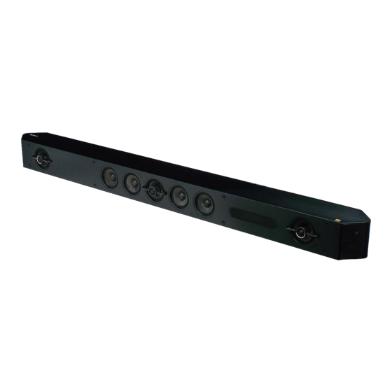
Photo: SA-ST9
HT-ST9
SA-ST9
SA-WST9
SPECIFICATIONS
BLUETOOTH section
Communication system
BLUETOOTH Specification version 3.0
Output
BLUETOOTH Specification Power Class 1
Maximum communication range
Line of sight approx. 30 m (98.4 ft)
1)
Maximum number of devices to be registered
9 devices
Frequency band
2.4 GHz band (2.4GHz - 2.4835 GHz)
Modulation method
FHSS (Freq Hopping Spread Spectrum)
2)
Compatible BLUETOOTH profiles
A2DP 1.2 (Advanced Audio Distribution Profile)
AVRCP 1.5 (Audio Video Remote Control Profile)
Supported Codecs
3)
SBC
4)
, AAC
5)
, LDAC
Transmission range (A2DP)
20 Hz - 20,000 Hz (Sampling frequency 44.1 kHz)
1)
The actual range will vary depending on factors such as obstacles
between devices, magnetic fields around a microwave oven, static
electricity, cordless phone use, reception sensitivity, the operating
system, software applications, etc.
2)
BLUETOOTH standard profiles indicate the purpose of BLUETOOTH
communication between devices.
3)
Codec: Audio signal compression and conversion format
4)
Subband Codec
5)
Advanced Audio Coding
Front L/Front R speaker blocks
Speaker system
2-way coaxial speaker system, Acoustic suspension
Speaker
Woofer: 65 mm (2 5/8 in) cone type, Magnetic fluid speaker
Tweeter: 18 mm (23/32 in) soft dome type
Center speaker block
Speaker system
Center
2-way coaxial speaker system, Acoustic suspension
Satellite
Full range speaker system, Acoustic suspension
Speaker (5 speakers)
Center
Woofer: 65 mm (2 5/8 in) cone type, Magnetic fluid speaker
Tweeter: 18 mm (23/32 in) soft dome type
Satellite
65 mm (2 5/8 in) cone type, Magnetic fluid speaker
General
Power requirements
120 V AC, 60 Hz (US and Canadian models)
120 V AC, 50 Hz/60 Hz (Taiwan model)
120 V - 240 V AC, 50 Hz/60 Hz (Latin American model)
220 V - 240 V AC, 50 Hz/60 Hz (Other models)
Power consumption
On: 60 W
Standby mode: 0.5 W or less
BLUETOOTH Standby mode: 0.5 W or less (Except AEP and UK models)
Networked Standby (all wired network ports connected, all wireless
network ports activated): 7.3 W (AEP and UK models)
HT-ST9
Canadian Model
Australian Model
Chinese Model
Singapore Model
Taiwan Model
Latin American Model
Dimensions (approx.) (w/h/d)
1,130 mm × 88 mm × 128 mm (44 1/2 in × 3 1/2 in × 5 1/8 in)
(without grille frame, without stands, including projection portion)
1,130 mm × 88 mm × 133 mm (44 1/2 in × 3 1/2 in × 5 1/4 in)
(with grille frame, without stands)
1,130 mm × 100 mm × 129 mm (44 1/2 in × 4 in × 5 1/8 in)
(without grille frame, with stands, including projection portion)
1,130 mm × 101 mm × 136 mm (44 1/2 in × 4 in × 5 3/8 in)
(with grille frame, with stands)
Mass (approx.)
6.8 kg (14 lb 15 7/8 oz) (without grille frame, without stands)
Compatible iPod/iPhone models
The compatible iPod/iPhone models are as follows. Update your iPod/
iPhone with the latest software before using with the system.
BLUETOOTH technology works with:
iPhone 6 Plus/iPhone 6/iPhone 5s/iPhone 5c/iPhone 5/iPhone 4s/
iPhone 4/iPhone 3GS
iPod touch (5th generation)/iPod touch (4th generation)
Wireless transmitter section
Communication system
Wireless Sound Specification version 3.0
Frequency band (Russian model)
5.2 GHz (5.180 GHz - 5.240 GHz)
Frequency band (Chinese model)
5.15 GHz - 5.25 GHz
Frequency band (Latin American, Singapore and Taiwan models)
5.8 GHz (5.736 GHz - 5.814 GHz)
Frequency band (Other models)
5.2 GHz (5.180 GHz - 5.240 GHz)
5.8 GHz (5.736 GHz - 5.814 GHz)
Modulation method
DSSS
– Continued on next page –
SOUND BAR
ACTIVE SPEAKER SYSTEM
SA-ST9
US Model
AEP Model
UK Model
HT-ST9
SA-ST9

Advertisement

Table of Contents
loading
Need help?

Need help?

Do you have a question about the HT-ST9 and is the answer not in the manual?

Questions and answers

Subscribe to Our Youtube Channel

Summary of Contents for Sony HT-ST9

  • Page 1 Ver. 1.1 2015.06 AEP Model UK Model Australian Model Chinese Model Singapore Model • All of the units included in the HT-ST9 (SA- Taiwan Model ST9/SA-WST9/Remote control) are required Photo: SA-ST9 to confi rming operation of SA-ST9. Check in Latin American Model advance that you have all of the units.
  • Page 2 Bluetooth SIG, Inc. and any use of such marks by Sony Corporation is under license. Other trademarks and trade names are those of their The source code for the software used in this product is subject to the respective owners.
  • Page 3 LES DIAGRAMMES SCHÉMATIQUES ET LA LISTE DES PIÈCES SONT CRITIQUES POUR LA SÉCURITÉ DE FONC- TIONNEMENT. NE REMPLACER CES COMPOSANTS QUE PAR DES PIÈCES SONY DONT LES NUMÉROS SONT DON- NÉS DANS CE MANUEL OU DANS LES SUPPLÉMENTS PUBLIÉS PAR SONY.
  • Page 4: Table Of Contents

    HT-ST9 TABLE OF CONTENTS SERVICING NOTES TEST MODE ......................45 DISASSEMBLY TROUBLESHOOTING .......... 53 2-1. Disassembly Flow ............10 2-2. Cover (Rear) Block ............12 DIAGRAMS 2-3. Rear Panel (L) Block ............13 5-1. Block Diagram - HDMI Section - ........57 2-4.
  • Page 5: Servicing Notes

    : Taiwan model ADVANCE PREPARATION WHEN CONFIRMING OP- ERATION All of the units included in the HT-ST9 (SA-ST9/SA-WST9/Re- – POWER Board (Conductor Side) – mote control) are required to confi rming operation of SA-ST9. Check in advance that you have all of the units.
  • Page 6 HT-ST9 NOTE OF REPLACING THE IC7004, IC7005, IC7007 11. Press the [ ] button on the remote commander, wait until the AND IC7008 ON THE AMP BOARD AND THE COM- display show “Status: Bluetooth Enable Successful!” (Screen PLETE AMP BOARD When IC7004, IC7005, IC7007 and IC7008 on the AMP board and 12.
  • Page 7 HT-ST9 2. Checking method of wireless LAN operation 12. When wired LAN connection is completed, “Physical Connec- tion: OK” and “Internet Access: OK” is displayed. Necessary Equipment: Note: Refer to the instruction manual about details of the setting method. •...
  • Page 8 HT-ST9 NOTES ON THE WIRELESS CONNECTION (LINK) AF- 6. Select “Reset to Factory Default Settings”, and press the [ ] TER REPAIRS ARE COMPLETE button on the remote commander. When the following replacing repair is performed, the link of the Bar speaker (SA-ST9) and Subwoofer (SA-WST9) is cut.
  • Page 9 HT-ST9 Ver. 1.1 BOND FIXATION OF ELECTRIC PARTS When the following parts are replaced, fi x the parts by using the bond (SC608Z2) (Refer to the fi gure below). Target parts: • AMP board: C7017, C7020, C7038, C7051, C7069, C7097, C7117, C7132, C7146, C7166 •...
  • Page 10: Disassembly

    HT-ST9 SECTION 2 DISASSEMBLY • This set can be disassembled in the order shown below. 2-1. DISASSEMBLY FLOW Note: When disassembling with the speaker side face down, make sure to install the grille assy. speaker side face Disassembling with the speaker side face down without installing the grille assy will damage the protrusion of the tweeter.
  • Page 11 HT-ST9 from page 10 2-15. RF MODULATOR BLOCK-1 (Page 24) 2-16. RF MODULATOR BLOCK-2 (Page 25) 2-17. RF MODULATOR BLOCK-3 (Page 26) 2-18. USB BOARD 2-20. CARD WLAN/BT COMBO (WIFI1) (Page 27) (Page 29) 2-19. WS BOARD, RF MODULATOR (RF1) (Page 28) 2-21.
  • Page 12: Cover (Rear) Block

    HT-ST9 Note: Follow the disassembly procedure in the numerical order given. 2-2. COVER (REAR) BLOCK How to install the connector Insert the connector straight into the interior. 2 two step screws There is a possibility that using this unit without (BVTP3 the connector correctly installed will damage it.
  • Page 13: Rear Panel (L) Block

    HT-ST9 2-3. REAR PANEL (L) BLOCK ow o i e or Note 4: When installing screws (B3 × 6), follow the installing procedure Insert the connector straight into the interior. in the numerical order given. There is a possibility that using this unit without the connector correctly installed will damage it.
  • Page 14: Rear Panel (R) Assy, Base Cover (Rear)

    HT-ST9 2-4. REAR PANEL (R) ASSY, BASE COVER (REAR) 1 two step 2 two screws Note 2: When installing screws, follow the installing procedure screws (BVTP3 in the numerical order given. 4 two screws 3 rear panel (R) assy (BVTP3...
  • Page 15: Panel (Side L, R)

    HT-ST9 2-6. PANEL (SIDE L, R) 1 Open the USB cover. Note 2: When installing screws (BVTP3 × 8), follow the installing procedure in the numerical order given. 3 two screws (BVTP3 6 panel (side R) 5 cushion (ABSO panel side) 4 Remove the panel (side R) block in the direction of the arrow.
  • Page 16: Panel (Bottom) Block

    HT-ST9 2-7. PANEL (BOTTOM) BLOCK 3 two screws Note 3: For the bracket (arm), install the screws in the (BVTP3 numerical order given in the figure below. 1 two screws 4 bracket (wall) assy (BVTP3 Top side Right side 1 two screws...
  • Page 17: Chassis Block-1

    HT-ST9 2-8. CHASSIS BLOCK-1 • Continued on 2-9 (page 18). two cushions (H15) 1 cushion (H15) Right side Top side 1 cushion (H15) 2 cushion (T05) – Rear view – Bottom side 1 three cushions (H15) Left side 1 two cushions...
  • Page 18: Chassis Block-2

    HT-ST9 2-9. CHASSIS BLOCK-2 9 DISPLAY board FFC (22P) (FFC4) (CN3003) 8 WLAN/BT card cable connector (CN502) 7 WS board cable connector (CN702) terminal side Right side 0 five screws (BVTP3 qa chassis block 6 USB board cable connector (CN501)
  • Page 19: Amp Board

    HT-ST9 2-10. AMP BOARD Note 2: When installing screws, follow the installing procedure in the numerical order given. 4 three screws (transistor) 6 screw 5 heat sink (AMP) 7 three screws (BVTP3 Note 1: When installing the heat sink (AMP), spread the compound...
  • Page 20: Io Board

    HT-ST9 2-11. IO BOARD astin osition of the c shion CN1701 cushion (T05) IO board Note 1: When installing screws (BVTP3 × 8), guide line follow the installing procedure in the 5 cushion (T05) numerical order given. – O boa bloc to iew –...
  • Page 21: Mb1406 Board

    HT-ST9 2-12. MB1406 BOARD Note 1: When the complete MB1406 board is replaced, refer to “NOTE OF REPLACING THE COMPLETE MB1406 BOARD OR CARD WLAN/BT COMBO” on page 6. Note 3: When installing screws (BVTP3 × 8), follow the installing procedure in the numerical order given.
  • Page 22: Power Cord (Ac1)

    HT-ST9 2-13. POWER CORD (AC1) 2 power cord connector (CN901) power board wiring stopper 1 Remove the power cord from the wiring stopper. groove power cord (AC1) Bottom side claw – – Left side 3 two claws wiring stopper power board –...
  • Page 23: Power Board

    HT-ST9 Ver. 1.1 2-14. POWER BOARD (Except US, CND, TW) nstallation position o the sheet (ins lation W POWER board bond 6 sheet JW905 (insulation JW905) sheet (insulation JW905) 2 screw (BV3 8 CU) 8 POWER board Note 1: When installing the POWER board, align the two guide pins and two holes.
  • Page 24: Rf Modulator Block-1

    HT-ST9 2-15. RF MODULATOR BLOCK-1 • Continued on 2-16 (page 25). guide line guide line REPEATER_REP2 board cable Note 3: When installing the REPEATER_REP2 board cable, pass the underneath of the L-ch speaker cable. guide line REPEATER_REP1 board cable guide line...
  • Page 25: Rf Modulator Block-2

    HT-ST9 2-16. RF MODULATOR BLOCK-2 • Continued on 2-17 (page 26). ee R guide line sheet (R) groove groove 3 sheet (R) Note 2: The sheet (R) is affixed using adhesive sheet. guide pin guide pin – view – 2 two canoe clips...
  • Page 26: Rf Modulator Block-3

    HT-ST9 2-17. RF MODULATOR BLOCK-3 leaf spring (cable) 2 Peel off the wire (WS) from the cushion (wire WS1). 3 cushion – – (wire WS1) Top side Note 3: When installing the leaf spring (cable), install so that it does touch the copper foil part of the wire.
  • Page 27: Usb Board

    HT-ST9 2-18. USB BOARD 2 two screws (BVTP3 3 USB board Note 1: When installing the USB board, align the hole and groove with the two guide pins. groove Note 2: When installing screws (BVTP3 × 8), follow the installing procedure in the numerical order given.
  • Page 28: Ws Board, Rf Modulator (Rf1)

    HT-ST9 2-19. WS BOARD, RF MODULATOR (RF1) Copper covered side. 1 connector (CN1401) 2 screw Note: When installing screws (BVTP3 × 8), follow the installing (BVTP3 procedure in the numerical order given. – RF modulator block rear bottom view –...
  • Page 29: Card Wlan/Bt Combo (Wifi1)

    HT-ST9 2-20. CARD WLAN/BT COMBO (WIFI1) Note 1: When the card WLAN/BT combo is replaced, refer to “NOTE OF REPLACING THE COMPLETE MB1406 BOARD OR CARD WLAN/BT COMBO” on page 6. guide line cushion (wire WIFI) Right side – –...
  • Page 30: Center Speaker Block

    HT-ST9 2-21. CENTER SPEAKER BLOCK Note 2: When installing the center speaker block, align the three guides and three grooves. guide guide guide groove groove groove 3 center speaker block 1 two step screws guide pin Right side guide guide...
  • Page 31: Front Speaker (R) Block

    HT-ST9 2-22. FRONT SPEAKER (R) BLOCK 1 two step screws Note 2: When installing the front speaker (R) 3 front speaker (R) block block, align the guide and groove. guide guide pin guide groove Right side Top side 2 three screws...
  • Page 32: Front Speaker (L) Block

    HT-ST9 2-23. FRONT SPEAKER (L) BLOCK Note 2: When installing the front speaker (L) block, align the guide and groove. guide Right side groove 3 front speaker (L) block 1 two step screws Top side Bottom side guide pin Note 1: Lay a soft piece of cloth...
  • Page 33: Grille Assy

    HT-ST9 2-24. GRILLE ASSY 1 boss 1 boss 1 two bosses 2 grille assy 1 two bosses 1 two bosses 2-25. NFC MODULE (NFC1) Left side speaker (R-ch) block Top side 1 Peel the NFC module block off of the speaker (R-ch) block.
  • Page 34: Display Board Block-1

    HT-ST9 2-26. DISPLAY BOARD BLOCK-1 • Continued on 2-27 (page 35). Note: When installing screws (BVTP3 × 12), follow the installing procedure in the numerical order given. n tallation po ition of the c hion (wire guide line 5 four screws...
  • Page 35: Display Board Block-2

    HT-ST9 2-27. DISPLAY BOARD BLOCK-2 How to install the b shin dam er Shape is round. Shape is not round. bushing (damper) bushing (damper) The lower side is the terminal side. 3 FFC (22P) (FFC4) (CN1304) 2 FFC (6P) (FFC5)
  • Page 36: Display Board, Oled Display (Oled1)

    HT-ST9 2-28. DISPLAY BOARD, OLED DISPLAY (OLED1) 2 Open the OLED display block 1 claw in the direction of the arrow. 1 claw 1 claw 1 claw 4 DISPLAY board 3 OLED display flexible board (CN1306) The lower side is the terminal side.
  • Page 37: Loudspeaker (Sp3, Sp4) (R-Ch)-1

    HT-ST9 2-29. LOUDSPEAKER (SP3, SP4) (R-ch)-1 • Continued on 2-30 (page 38). 2 seven screws (3.5) 1 two screws (3.5) 1 screw (3.5) Left side 1 screw (3.5) 1 two screws (3.5) 2 screw (3.5) 1 screw Top side (3.5) 2 screw (3.5)
  • Page 38: Loudspeaker (Sp3, Sp4) (R-Ch)-2

    HT-ST9 2-30. LOUDSPEAKER (SP3, SP4) (R-ch)-2 7 loudspeaker (18 mm) Installation direction for (tweeter (front Rch)) the woofer speaker wire (SP3) Note 1: When installing the speaker wire, 6 terminal make the position of caulking of 1 Lift up the loudspeaker (SP3) [black] terminals is outside.
  • Page 39: Loudspeaker (Sp1, Sp2) (L-Ch)-1

    HT-ST9 2-31. LOUDSPEAKER (SP1, SP2) (L-ch)-1 • Continued on 2-32 (page 40). 2 seven screws (3.5) 1 screw 1 two screws Right side (3.5) (3.5) 1 screw (3.5) 1 two screws (3.5) 2 screw (3.5) 1 screw Top side (3.5) 2 screw (3.5)
  • Page 40: Loudspeaker (Sp1, Sp2) (L-Ch)-2

    HT-ST9 2-32. LOUDSPEAKER (SP1, SP2) (L-ch)-2 Installation direction for 7 loudspeaker (18 mm) the woofer speaker wire (tweeter (front Lch)) 1 Lift up the loudspeaker (SP1) (SP1) Note 1: When installing the speaker wire, in the direction of the arrow.
  • Page 41: Loudspeaker (Sp5, Sp6, Sp7, Sp8) (Center)

    HT-ST9 2-33. LOUDSPEAKER (SP5, SP6, SP7, SP8) (CENTER) Installation direction for the woofer speaker wire Note 1: When installing the speaker wire, 4 loudspeaker (6.5 cm) make the position of caulking of (surround (Lch)) (SP6) terminals is outside. 1 four screws (3.5)
  • Page 42: Loudspeaker (Sp9, Sp10) (Center)-1

    HT-ST9 2-34. LOUDSPEAKER (SP9, SP10) (CENTER)-1 • Continued on 2-35 (page 43). 2 cushion (absorbent) 2 cushion (absorbent) 1 two screws (3.5) 1 screw (3.5) Left side 1 screw (3.5) 1 two screws (3.5) 2 cushion (absorbent) 2 cushion (absorbent) 1 screw (3.5)
  • Page 43: Loudspeaker (Sp9, Sp10) (Center)-2

    HT-ST9 2-35. LOUDSPEAKER (SP9, SP10) (CENTER)-2 Installation direction for 1 Lift up the loudspeaker (SP10) 8 loudspeaker (18 mm) the woofer speaker wire (tweeter (center)) (SP10) in the direction of the arrow. Note 1: When installing the speaker wire, make the position of caulking of 4 loudspeaker (6.5 cm)
  • Page 44: Connection Cable With Speaker (Spc3, Spc4)

    HT-ST9 2-36. CONNECTION CABLE WITH SPEAKER (SPC3, SPC4) Left side cabinet (center) 1 Remove three cord bushings of connection cable with speaker Top side in the direction of the arrow. 2 connection cable with speaker (SPC4) Bottom side Right side –...
  • Page 45: Test Mode

    HT-ST9 SECTION 3 TEST MODE COLD RESET Releasing method: It can initialize various backup information. Perform the “COLD RESET”. Note 3: The demo mode does not release by unplug the AC cord. Procedure: DEMO MODE2 1. Press the [ ] button to turn the power on.
  • Page 46 HT-ST9 Ver. 1.1 When pressing the all buttons, “OK” and “K 5” are alternately 3. The message “MSURE” is displayed on the OLED display and displayed on the OLED display. enter the AMP setting and measurement mode. MSURE 4. Each time the [DIMMER] button on the remote commander is pressed, the swap mode changes from FULL →...
  • Page 47 HT-ST9 7. Each time the [CLEAR AUDIO+] button on the remote com- BD SERVICE MODE mander is pressed, VACS on/off setting is changed. Note: The operation in this mode must use a remote commander and TV monitor. VAOFF Setting method of the BD service mode: 1.
  • Page 48 HT-ST9 2. Menu Tree Service Mode Menu Device Test Diag Service Mode Menu [1] Diag [1] Diag [2] Log [2] Log [3] Factory Initialize [3] Factory Initialize [4] Network [4] Network Video Test [5] Version Up [5] Version Up Not used...
  • Page 49 HT-ST9 3. Service Mode Menu (Top Menu) Diag This is the top menu of service mode. Device Test Each function is accessed from this screen. Category: Operation: ] Moves the cursor Diag Moves to the screen of the item selected with the cursor...
  • Page 50 HT-ST9 7. Diag (Wireless LAN Test) Diag This screen performs wireless LAN/Miracast test. Category: Wireless LAN Test Screen 1: Selects the wireless LAN test category Operation: Diag Selects the category < Category: Wireless LAN Test ]/[ ] Moves to the selected category...
  • Page 51 HT-ST9 Screen 4: Select (3) Write Bluetooth device address to (Screen 6) Diag Registry Category: Wireless LAN Test (Displayed characters/values in the following fi gure are example) [1] Show WLAN HwInfo It records the address of the Bluetooth device. [2] Connect to AccessPoint •...
  • Page 52 HT-ST9 12. Log: Error Log (Output of each Log) 16. Version UP Note: Not used for the servicing. This screen displays the contents of each log. Note: Do not refer to the displayed date. 17. System Information (System Information Display) Screen 1: Selects log This screen displays system information.
  • Page 53: Troubleshooting

    HT-ST9 SECTION 4 TROUBLESHOOTING 1. “PRTCT” is displayed on the OLED display after turning the power on “PRTCT”, “PUSH” and “POWER” display alternately in the OLED display after turning the power on. IC7004, IC7005, IC7007, IC7008 Replace the IC7004, IC7005, on the AMP board is burned out.
  • Page 54 HT-ST9 2. The sound is not outputted In the following settings, it is checked whether the sound outputted. (Connect this unit with TV monitor) The sound is not outputted. Home screen to display, to enter the setting screen by selecting the “Setup”.
  • Page 55 HT-ST9 4. Power is not turned on (OLED display does not appear) Power is not turned on. (OLED display does not appear) The voltage of the following is 28 V. POWER board: CN904 pin 3 to 5 Fuse (F901) on the POWER board...
  • Page 56 HT-ST9 MEMO...
  • Page 57: Diagrams

    HT-ST9 SECTION 5 DIAGRAMS 5-1. BLOCK DIAGRAM - HDMI Section - HDMI TRANSCEIVER HDMI RECEIVER IC3506 IC5001 DATA0+ 12 RX0P TX0P 43 32 R2X1– DATA0– 11 RX0N TX0N 42 33 R2X1+ HDMI TRANSMITTER IC101 (1/3) IC5010 DATA1+ 14 RX1P TX1P 45 30 R2X0–...
  • Page 58: Block Diagram - Memory/Main Section

    HT-ST9 5-2. BLOCK DIAGRAM - MEMORY/MAIN Section - NS_XTALO IC101 (2/3) X401 27MHz NS_XTALI SD-RAM IC102 DQL0 - DQL7, RDQ0 - RDQ15 DQU0 - DQU7 OPTICAL D0A0 - D0A14 RECEIVER B23 OPTICAL A0 - A13, NC RA0 - RA14 DIGITAL IN...
  • Page 59: Block Diagram - Amp Section

    HT-ST9 5-3. BLOCK DIAGRAM - AMP Section - TWEETER STREAM PROCESSOR DIGITAL POWER AMP (FRONT L-CH) IC7006 IC7004 D1, D2, D3, D4, MCK, LRCK, BCK >002B 24 SDIN1 PWM_P_6 5 INPUT_A OUT_A L.P.F. 25 SDIN2 PWM_M_6 6 INPUT_B OUT_A WOOFER...
  • Page 60: Block Diagram - Panel/Power Supply Section

    HT-ST9 Ver. 1.1 5-4. BLOCK DIAGRAM - PANEL/POWER SUPPLY Section - SYSTEM CONTROLLER OLED1 IC3004 (4/4) OLED DISPLAY B+ SWITCH SP_3.3V Q307, 312 SDIN 14 FL (O-LED)_DOUT DC/DC CONVERTER IC305 SCLK 15 FL (O-LED)_CLK SPARTA_PCONT 12 FL (O-LED)_CS VREF_0.75V 5 OLED_DS B+ SWITCH DDR_1.5V...
  • Page 61 HT-ST9 Ver. 1.1 THIS NOTE IS COMMON FOR PRINTED WIRING BOARDS AND SCHEMATIC DIAGRAMS. • Circuit Boards Location (In addition to this, the necessary note is printed in each block.) REPEATER_REP2 board For Printed Wiring Boards. For Schematic Diagrams. Note: Note: •...
  • Page 62: Printed Wiring Board - Mb1406 Board

    HT-ST9 5-5. PRINTED WIRING BOARD - MB1406 Board - • See page 61 for Circuit Boards Location. • : Uses unleaded solder. S3001 WIFI1 DISPLAY (Page 68) >07P CARD BOARD (Page 67) >06P BOARD WLAN/BT COMBO CN1304 MB1406 BOARD (SIDE A)
  • Page 63: Printed Wiring Board - Amp Board

    HT-ST9 Ver. 1.1 5-6. PRINTED WIRING BOARD - AMP Board - • See page 61 for Circuit Boards Location. • : Uses unleaded solder. AMP BOARD (SIDE A) (CHASSIS) R7043 R7048 C7189 R7045 CL7015 LN7006 R7042 LN7003 R7058 C7003 C7077...
  • Page 64: Schematic Diagram - Amp Section (1/2)

    HT-ST9 Ver. 1.1 5-7. SCHEMATIC DIAGRAM - AMP Section (1/2) - • See page 72 for Waveforms. • See page 72 for IC Block Diagrams. (Page 65) >001S BOARD (2/2) AMP BOARD (1/2) CN7001 CL7002 JL7047 VACS_REQ CL7003 PVDD_28V JL7003 PVDD_28V >01S...
  • Page 65: Schematic Diagram - Amp Section (2/2)

    HT-ST9 Ver. 1.1 5-8. SCHEMATIC DIAGRAM - AMP Section (2/2) - • See page 72 for IC Block Diagrams. TWEETER WOOFER TWEETER WOOFER SP10 (FRONT L-CH) (FRONT L-CH) (FRONT R-CH) (FRONT R-CH) SURROUND SURROUND SURROUND SURROUND WOOFER TWEETER R-CH L-CH...
  • Page 66: Printed Wiring Boards - Io/Usb Section

    HT-ST9 5-9. PRINTED WIRING BOARDS - IO/USB Section - 5-10. SCHEMATIC DIAGRAM - IO/USB Section - • See page 61 for Circuit Boards Location. • : Uses unleaded solder. IO BOARD CN1702 IO BOARD IO BOARD (COMPONENT SIDE) (CONDUCTOR SIDE)
  • Page 67: Printed Wiring Board - Ws Board

    HT-ST9 5-11. PRINTED WIRING BOARD - WS Board - • See page 61 for Circuit Boards Location. • : Uses unleaded solder. WS BOARD WS BOARD (SIDE A) (SIDE B) RF MODULATOR (WS001) FFC3 CN1402 JL1411 C1404 JL1419 JL1421 C1412...
  • Page 68: Printed Wiring Boards - Display Section

    HT-ST9 5-13. PRINTED WIRING BOARDS - DISPLAY Section - • See page 61 for Circuit Boards Location. • : Uses unleaded solder. NFC1 NFC MODULE MB1406 BOARD (RC-S730) >07P BOARD (Page 62) DISPLAY BOARD CN3003 (SIDE A) FFC5 FFC4 CN1305...
  • Page 69: Schematic Diagram - Display Section

    HT-ST9 5-14. SCHEMATIC DIAGRAM - DISPLAY Section - DISPLAY BOARD CN1306 CN1303 R1314 SDIN JL1301 R1315 KEY2 SCLK JL1302 R1316 KEY1 JL1303 R1317 BOARD KEY0 RSTB R1318 DGND OLED1 OLED DISPLAY CN1304 C1306 JL1326 JL1304 R1319 OLED_DC JL1305 R1307 620k...
  • Page 70: Printed Wiring Board - Power Board

    HT-ST9 Ver. 1.1 5-15. PRINTED WIRING BOARD - POWER Board - • See page 61 for Circuit Boards Location. • : Uses unleaded solder. POWER BOARD C902 (Except US, CND, TW) C940 C989 (US, CND, TW) F931 ET931 C994 ET932...
  • Page 71: Schematic Diagram - Power Board

    HT-ST9 Ver. 1.1 5-16. SCHEMATIC DIAGRAM - POWER Board - • See page 72 for IC Block Diagrams. POWER BOARD ET931 JL904 (Except US, CND, TW) (US, CND, TW) C902 C903 C989 C990 (CHASSIS) 0.0022 0.0022 0.001 0.001 250V 250V...
  • Page 72 HT-ST9 Ver. 1.1 • Waveforms • IC Block Diagrams IC7004, 7005, 7007, 7008 TAS5624ADDVR – POWER Board – IC930 STR-Y6735 – AMP Board – – AMP Board – (US, Canadian and Taiwan models) GVDD_AB 1 BST_A BST_B IC7001 RT7272BGSP IC930 STR-Y6766B...
  • Page 73: Exploded Views

    HT-ST9 Ver. 1.1 SECTION 6 EXPLODED VIEWS Note: • -XX and -X mean standardized parts, so • The mechanical parts with no reference The components identifi ed by mark 0 they may have some difference from the number in the exploded views are not sup- or dotted line with mark 0 are critical for original one.
  • Page 74: Side Panel Section

    HT-ST9 Ver. 1.1 6-2. SIDE PANEL SECTION • Rear bottom view not supplied chassis section not supplied not supplied not supplied supplied not supplied not supplied not supplied not supplied not supplied not supplied not supplied not supplied 51 54...
  • Page 75: Chassis Section

    HT-ST9 Ver. 1.1 6-3. CHASSIS SECTION • Rear bottom view not supplied (IO board) not supplied FFC2 (9 pin) not supplied not supplied FFC1 not supplied (28 pin) not supplied not supplied (Except US, CND, TW) not supplied not supplied...
  • Page 76: Front Block Section

    HT-ST9 6-4. FRONT BLOCK SECTION • Rear bottom view 153 153 not supplied not supplied (USB board) not supplied supplied not supplied (WS board) not supplied not supplied not supplied not supplied FFC3 not supplied center speaker section (26 pin)
  • Page 77: Center Speaker Section

    HT-ST9 6-5. CENTER SPEAKER SECTION • Front bottom view 201 201 201 201 201 201 SP10 not supplied 201 201 not supplied 201 201 not supplied not supplied not supplied not supplied not supplied SPC3 SPC4 Ref. No. Part No.
  • Page 78: Speaker (L-Ch) Section

    HT-ST9 6-6. SPEAKER (L-ch) SECTION • Front bottom view not supplied not supplied not supplied (MOUNTED board) not supplied not supplied not supplied SPC1 not supplied Ref. No. Part No. Description Remark Ref. No. Part No. Description Remark 4-986-971-02 SCREW (3.5)
  • Page 79: Display Board Section

    HT-ST9 6-7. DISPLAY BOARD SECTION • Front bottom view not supplied FFC4 OLED1 (22 pin) not supplied not supplied not supplied not supplied not supplied not supplied FFC5 (6 pin) speaker (R-ch) section NFC1 Note: As for WIRE KIT (FFC/SA-ST9), all fl at fl exible cables (Ref. No.
  • Page 80: Speaker (R-Ch) Section

    HT-ST9 6-8. SPEAKER (R-ch) SECTION • Front bottom view 351 351 not supplied not supplied not supplied (MOUNTED board) not supplied not supplied not supplied SPC2 not supplied Ref. No. Part No. Description Remark Ref. No. Part No. Description Remark 4-986-971-02 SCREW (3.5)
  • Page 81: Front Panel Section

    HT-ST9 6-9. FRONT PANEL SECTION • Rear bottom view not supplied not supplied not supplied not supplied not supplied not supplied not supplied not supplied not supplied not supplied not supplied not supplied not supplied not supplied not supplied not supplied...
  • Page 82: Electrical Parts List

    HT-ST9 Ver. 1.1 SECTION 7 ELECTRICAL PARTS LIST Note: • Due to standardization, replacements in • SEMICONDUCTORS The components identifi ed by mark 9 con- In each case, u: μ, for example: the parts list may be different from the tain confi...
  • Page 83 HT-ST9 Ver. 1.1 Ref. No. Part No. Description Remark Ref. No. Part No. Description Remark C7078 1-127-948-21 FILM CHIP 0.0047uF C7149 1-112-692-11 CERAMIC CHIP 1000PF C7079 1-118-386-11 CERAMIC CHIP 0.1uF C7151 1-118-365-11 CERAMIC CHIP 0.047uF C7080 1-112-692-11 CERAMIC CHIP 1000PF...
  • Page 84 HT-ST9 Ref. No. Part No. Description Remark Ref. No. Part No. Description Remark < IC > R7004 1-218-973-11 METAL CHIP 1/16W R7005 1-218-967-11 METAL CHIP 1/16W IC7001 6-721-694-01 IC RT7272BGSP R7006 1-218-969-11 METAL CHIP 1/16W IC7002 6-716-993-01 IC MM1836A33NRE IC7003...
  • Page 85 HT-ST9 DISPLAY Ref. No. Part No. Description Remark Ref. No. Part No. Description Remark R7067 1-218-937-11 METAL CHIP 1/16W < CONNECTOR > R7068 1-218-937-11 METAL CHIP 1/16W R7069 1-218-937-11 METAL CHIP 1/16W CN1303 1-580-057-11 PIN, CONNECTOR (SMD) 4P CN1304 1-816-649-51...
  • Page 86 0 D941 8-719-083-71 DIODE UDZSUSTE-1730B 0 C905 1-114-594-21 FILM 0.22uF 310V (See Note 2) 0 D942 6-503-775-01 DIODE CRH02 (T5R, SONY, XM) 0 C907 1-116-397-21 FILM 0.33uF 310V D951 6-502-961-01 DIODE DA2J10100L (Except US, CND, TW) (See Note 2) D952...
  • Page 87 HT-ST9 Ver. 1.1 POWER REPEATER_REP1 REPEATER_REP2 Ref. No. Part No. Description Remark Ref. No. Part No. Description Remark < FUSE > 0 R997 1-216-864-91 SHORT CHIP 0 (US, CND, TW) 0 F901 1-523-067-51 FUSE (5 A/250 V) < TRANSFORMER >...
  • Page 88 HT-ST9 Ver. 1.1 Ref. No. Part No. Description Remark Ref. No. Part No. Description Remark * C1409 1-118-035-11 CERAMIC CHIP 0.1uF MISCELLANEOUS C1412 1-164-866-11 CERAMIC CHIP 47PF ************** C1414 1-100-354-21 ELECT CHIP 220uF 6.3V C1415 1-100-354-21 ELECT CHIP 220uF 6.3V...
  • Page 89 HT-ST9 Ver. 1.1 Ref. No. Part No. Description Remark ACCESSORIES ************ Grille frame (1) Remote control (1) 4-558-496-12 STARTUP GUIDE (ENGLISH, FRENCH) (US, CND) 4-558-496-22 STARTUP GUIDE (ENGLISH) (UK) 4-558-496-32 STARTUP GUIDE (FRENCH, SPANISH, DUTCH) (AEP) 4-558-496-42 STARTUP GUIDE (GERMAN, ITALIAN, POLISH)
  • Page 90 HT-ST9 MEMO...
  • Page 91 HT-ST9 HT-ST9 2. DIAGRAMS SA-ST9 THIS NOTE IS COMMON FOR PRINTED WIRING BOARDS. (In addition to this, the necessary note is printed in each block.) For Printed Wiring Boards. US Model Note: Canadian Model • X : Parts extracted from the component side.
  • Page 92 HT-ST9 2-1. PRINTED WIRING BOARD - MB1406 Board - • : Uses unleaded solder. WIFI1 DISPLAY Refer to page CARD Refer to page >07P BOARD 68 on original >06P WLAN/BT COMBO BOARD 67 on original CN1304 service manual MB1406 BOARD...
  • Page 93 HT-ST9 MEMO...
  • Page 94 HT-ST9 REVISION HISTORY Ver. Date Description of Revision 2015.02 2015.06 Addition of Chinese, Russian, Singapore, Taiwan and Latin American models Addition of BOND FIXATION OF ELECTRIC PARTS Change of Part for COVER (REAR) (Ref. No. 8) Change of Part No. for PANEL (SIDE R) ASSY (for R-ch) (Ref. No. 55) Change of Part No.

This manual is also suitable for:

Sa-st9Sa-wst9

Table of Contents