Table of Contents
Advertisement
Available languages
Available languages
Quick Links
Istruzioni per installazione, uso e manutenzione
Installation, use and maintenance instructions
Bruciatori di gasolio
I
Light oil burners
GB
Funzionamento bistadio
Two stage operation
CODICE - CODE
3475032
3475033
3475232
3475233
3475432
3475433
MODELLO - MODEL
RL 70
RL 70
RL 100
RL 100
RL 130
RL 130
TIPO - TYPE
660 T1
660 T1
661 T1
661 T1
662 T1
662 T1
20111051 (1) - 09/2015
Advertisement
Chapters
Table of Contents

Related Manuals for Riello RL Series


Summary of Contents for Riello RL Series
- Page 1 Istruzioni per installazione, uso e manutenzione Installation, use and maintenance instructions Bruciatori di gasolio Light oil burners Funzionamento bistadio Two stage operation CODICE - CODE MODELLO - MODEL TIPO - TYPE 3475032 RL 70 660 T1 3475033 RL 70 660 T1 3475232 RL 100 661 T1...
-
Page 3: Table Of Contents
Indice Dichiarazioni ....................................2 Informazioni ed avvertenze generali ............................3 Informazioni sul manuale di istruzione ................................3 Garanzia e responsabilità .....................................4 Sicurezza e prevenzione................................5 Premessa ........................................5 Addestramento del personale ..................................5 Descrizione tecnica del bruciatore ............................6 Dati tecnici........................................6 Dati elettrici ........................................6 Descrizione bruciatore (Fig. -
Page 4: Dichiarazioni
La qualità viene garantita mediante un sistema di qualità e management certificato secondo UNI EN ISO 9001. Dichiarazione del costruttore RIELLO S.p.A. dichiara che i seguenti prodotti rispettano i valori limite di emissione di NOx imposti dalla normativa tedesca “1. BImSchV revisione 26.01.2010”. -
Page 5: Informazioni Ed Avvertenze Generali
Informazioni ed avvertenze generali Informazioni ed avvertenze generali Informazioni sul manuale di istruzione Introduzione 2.1.2 Pericolo componenti in tensione Il manuale di istruzione dato a corredo del bruciatore: Questo simbolo contraddistingue operazioni che, ➤ costituisce parte integrante ed essenziale del prodotto e se non correttamente eseguite, comportano scos- non va da esso separato;... -
Page 6: Garanzia E Responsabilità
Informazioni ed avvertenze generali Garanzia e responsabilità garantisce i suoi prodotti nuovi dalla data dell’installazio- ne secondo le normative vigenti e/o in accordo con il contratto di vendita. Verificare, all’atto della prima messa in funzione, che il bruciatore sia integro e completo. La mancata osservanza a quanto descritto in que- sto manuale, la negligenza operativa, una errata installazione e l’esecuzione di modifiche non au-... -
Page 7: Sicurezza E Prevenzione
Sicurezza e prevenzione Sicurezza e prevenzione Premessa Addestramento del personale I bruciatori sono stati progettati e costruiti in conformità L’utente è la persona, o l’ente o la società, che ha acquistato la alle norme e direttive vigenti, applicando le regole tecniche di si- macchina e che intende usarla per gli usi concepiti allo scopo. -
Page 8: Descrizione Tecnica Del Bruciatore
Descrizione tecnica del bruciatore Descrizione tecnica del bruciatore Dati tecnici MODELLO RL 70 RL 100 RL 130 TIPO 660 T1 661 T1 662 T1 POTENZA stadio 2° 474 - 830 711 - 1186 948 - 1540 408 - 714 612 - 1020 816 - 1325 PORTATA Mcal/h... - Page 9 Descrizione tecnica del bruciatore 4.2.1 Versioni costruttive Lunghezza Alimentazione Modello Codice boccaglio elettrica 3475030 - 3475032 trifase RL 70 3475031 - 3475033 trifase 3475230 - 3475232 trifase RL 100 3475231 - 3475233 trifase 3475430 - 3475432 trifase RL 130 3475431 - 3475433 trifase 4.2.2 Accessori (su richiesta) :...
-
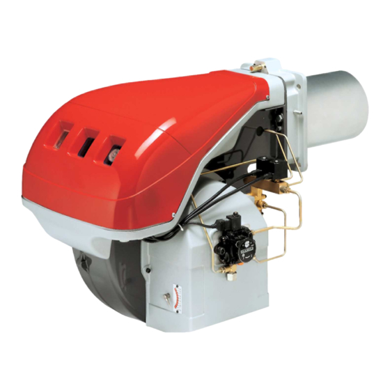
Page 10: Descrizione Bruciatore (Fig. 1)
Descrizione tecnica del bruciatore Descrizione bruciatore (Fig. 1) Elettrodi di accensione Testa di combustione Vite per regolazione testa di combustione Vite per il fissaggio ventilatore alla flangia Guide per apertura bruciatore ed ispezione alla testa di combustione Elettrovalvola di sicurezza Pompa Ingresso aria nel ventilatore Serranda aria... - Page 11 Descrizione tecnica del bruciatore 4.3.2 Ingombro (Fig. 2) - misure indicative L’ingombro del bruciatore è riportato in (Fig. 2). Tener presente che per ispezionare la testa di combustione il bru- ciatore deve essere aperto arretrandone la parte posteriore sulle guide. L’ingombro del bruciatore aperto è...
-
Page 12: Campi Di Lavoro (Fig. 3)
Descrizione tecnica del bruciatore Campi di lavoro (Fig. 3) I bruciatori RL 70-100-130 possono funzionare in due modi: mo- D687 nostadio e bistadio. La PORTATA del 1° stadio va scelta entro l’area A dei diagram- mi a lato. La PORTATA del 2° stadio va scelta entro l’area B (e C per RL 130). -
Page 13: Installazione
ATTENZIONE La manomissione, l’asportazione, la mancanza della targhetta del bruciatore o quant’altro non permettono la sicura identificazione del bruciatore RIELLO S.p.A. 0036 I−37045 Legnago (VR) ATTENZIONE e rendono difficoltosa qualsiasi operazione di in- stallazione e manutenzione. -
Page 14: Piastra Caldaia (Fig. 6)
Installazione Piastra caldaia (Fig. 6) Forare la piastra di chiusura della camera di combustione come in (Fig. 6). La posizione dei fori filettati può essere tracciata utiliz- zando lo schermo termico a corredo del bruciatore. RL 70 275-325 M 12 RL 100 275-325 M 12... -
Page 15: Scelta Degli Ugelli Per Il 1° E 2° Stadio
Installazione Scelta degli ugelli per il 1° e 2° stadio Entrambi gli ugelli vanno scelti tra quelli indicati nella tabella Esempio con RL 70 (Tab. B). Potenza caldaia = 635 kW - rendimento 90 % Il primo ugello determina la portata del bruciatore in 1° stadio. Potenza richiesta al bruciatore = Il secondo ugello funziona assieme al primo ed entrambi deter- 635 : 0,9... -
Page 16: Montaggio Degli Ugelli
Installazione Montaggio degli ugelli A questo punto dell’installazione il bruciatore è ancora separato dal boccaglio; è perciò possibile montare i due ugelli con la chia- ve a tubo 1) (Fig. 9) (da 16 mm), dopo aver tolto i tappi in plastica 2) (Fig. -
Page 17: Regolazione Testa Di Combustione
Installazione Regolazione testa di combustione La regolazione della testa di combustione dipende unicamente dalla portata del bruciatore in 2° stadio, cioè dalla portata dei due ugelli scelti a pag. 13. Ruotare la vite 4) (Fig. 13) fino a far collimare la tacca indicata dal diagramma (Fig. -
Page 18: Impianto Elettrico
Impianto elettrico Impianto elettrico Note sulla sicurezza per i collegamenti elettrici ➤ I collegamenti elettrici devono essere eseguiti in assenza di alimentazione elettrica. ➤ I collegamenti elettrici devono essere eseguiti secondo le norme vigenti del paese di destinazione e da perso- nale qualificato. -
Page 19: Collegamenti Elettrici
Impianto elettrico Collegamenti elettrici Eseguiti dall’installatore Usare cavi flessibili secondo norma EN 60 335-1: ➤ se sotto guaina di PVC almeno tipo H05 VV-F ➤ se sotto guaina di gomma almeno tipo H05 RR-F. Tutti i cavi da collegare alla morsettiera 8) (Fig. 15) del bruciatore vanno fatti passare dai passacavi. -
Page 20: Impianto Idraulico
Impianto idraulico Impianto idraulico Alimentazione combustibile Circuito ad anello Il circuito ad anello è costituito da un condotto che parte dalla ci- sterna e ritorna in essa nel quale una pompa ausiliaria fa scorrere il combustibile sotto pressione. Una derivazione dall’anello ali- menta il bruciatore. -
Page 21: Collegamenti Idraulici (Fig. 17)
Impianto idraulico Collegamenti idraulici (Fig. 17) La pompa ha un by-pass che mette in comunicazione il ritorno con l’aspirazione. È installata sul bruciatore con il by-pass chiuso dalla vite 6) (Fig. 24 pag. 22). È quindi necessario collegare entrambi i tubi flessibili alla pompa. Se la pompa viene fatta funzionare con il ritorno chiuso e la vite di by-pass inserita, si guasta immediatamente. -
Page 22: Regolazione Bruciatore
Regolazione bruciatore Regolazione bruciatore Accensione Verificare la corretta funzionalità dei dispositivi di Bruciatore Stadio regolazione, comando e sicurezza. Spento 1° ATTENZIONE Mettere l’interruttore 1) (Fig. 19) in posizione "ACCESO". Acceso 2° Alla prima accensione, all’atto del passaggio dal 1° al 2° stadio, Fig. - Page 23 Regolazione bruciatore Senza otturatore 4) (Fig. 8 pag. 12) RL 70 RL 100 RL 130 NOTA: kg/h mbar kg/h mbar kg/h mbar per facilitare la regolazione degli esagoni 2) e 4) (Fig. 21), servirsi della chiave esagona da 3 mm 5) (Fig. 21). 11,0 11,0 Tab.
- Page 24 Regolazione bruciatore 8.2.1 Avviamento bruciatore (Fig. 23) - (Fig. 24) 8.2.2 Funzionamento a regime Impianto dotato di un telecomando TR D705 Terminato il ciclo di avviamento, il comando dell’elettrovalvola di 2° stadio passa al telecomando TR che controlla la pressione o la temperatura in caldaia.
-
Page 25: Manutenzione
Manutenzione Manutenzione Note sulla sicurezza per la manutenzione Filtri (Fig. 25) La manutenzione periodica è essenziale per il buon funziona- Controllare i cestelli filtranti: mento, la sicurezza, il rendimento e la durata del bruciatore. • di linea 1) • in pompa 2) • all’ugello 3), pulirli o sostituirli. Essa consente di ridurre i consumi, le emissioni inquinanti e di Se all’interno della pompa si notano ruggine o altre impurità, aspi- mantenere il prodotto affidabile nel tempo. - Page 26 Manutenzione Visore fiamma (Fig. 27) Eventuale sostituzione pompa e/o giunti (Fig. 29) Pulire il vetrino quando è necessario. Eseguire il montaggio rispettando le indicazioni delle figure (Fig. 29). D709 D1108 Fig. 29 Fig. 27 Tubi flessibili Controllare che il loro stato sia buono, che non siano stati calpe- stati o deformati.
-
Page 27: Diagnostica Programma Di Avviamento
Manutenzione Diagnostica programma di avviamento Durante il programma di avviamento, le indicazioni sono esplica- te nella seguente tabella: Tabella codice colore Sequenze Codice colore Preventilazione Fase di accensione Funzionamento con fiamma ok Funzionamento con segnale di fiamma debole Alimentazione elettrica inferiore a ~ 170V Blocco Luce estranea Legenda:... -
Page 28: Diagnostica Software
Manutenzione Diagnostica software Fornisce l’analisi della vita del bruciatore mediante collegamento ottico a PC indicandone ore di funzionamento, numero e tipologie di blocchi, numero di serie dell’apparecchiatura etc… Per visualizzare la diagnostica procedere come segue: – Tenere premuto il pulsante per più di 3 secondi dalla condizione di led rosso fisso (blocco bruciatore). Il termine dell’operazione verrà... - Page 29 Manutenzione SEGNALE INCONVENIENTE CAUSA PROBABILE RIMEDIO CONSIGLIATO 7 lampeggi Stacco fiamma 34 - Testa mal regolata......Regolarla, vedi pag. 15, Fig. 14 35 - Elettrodi d’accensione mal regolati o sporchi .
-
Page 30: Appendice - Schema Quadro Elettrico
Appendice - Schema quadro elettrico Appendice - Schema quadro elettrico Indice schemi Indicazione riferimenti Schema funzionale Schema funzionale Collegamenti elettrici a cura dell’installatore Indicazione riferimenti / 1 .A 1 N. foglio Coordinate 20111051... - Page 31 Contents Declarations....................................2 Information and general instructions............................3 Information about the instruction manual ..............................3 Guarantee and responsibility ..................................4 Safety and prevention................................5 Introduction ........................................5 Personnel training ......................................5 Technical description of the burner ............................6 Technical data.......................................6 Electrical data........................................6 Burner description (Fig. 1).....................................8 Firing rates (Fig.
-
Page 32: Declarations
The quality is guaranteed by a quality and management system certified in accordance with UNI EN ISO 9001. Manufacturer's Declaration RIELLO S.p.A. declares that the following products comply with the NOx emission limits specified by German standard “1. BImSchV revision 26.01.2010”. -
Page 33: Information And General Instructions
Information and general instructions Information and general instructions Information about the instruction manual Introduction 2.1.2 Danger: live components The instruction manual supplied with the burner: This symbol indicates operations which, if not car- ➤ is an integral and essential part of the product and must not ried out correctly, lead to electric shocks with le- be separated from it;... -
Page 34: Guarantee And Responsibility
Information and general instructions Guarantee and responsibility guarantees its new products from the installation date, in accordance with the regulations in force and/or the sales con- tract. At the moment of the first start-up, check that the burner is integral and complete. Failure to observe the information given in this manual, operating negligence, incorrect installa- tion and the carrying out of non authorised modifi-... -
Page 35: Safety And Prevention
Safety and prevention Safety and prevention Introduction Personnel training burners have been designed and built in compliance The user is the person, body or company that has acquired the with current regulations and directives, applying the known tech- machine and intends to use it for the specific purpose. He is re- nical rules of safety and envisaging all the potential danger situ- sponsible for the machine and for the training of the people work- ations. -
Page 36: Technical Description Of The Burner
Technical description of the burner Technical description of the burner Technical data MODEL RL 70 RL 100 RL 130 TYPE 660 T1 661 T1 662 T1 OUTPUT 2nd stage 474 - 830 711 - 1186 948 - 1540 408 - 714 612 - 1020 816 - 1325 DELIVERY... - Page 37 Technical description of the burner 4.2.1 Variants Power supply Length of Model Code electrical blast tube mm 3475030 - 3475032 Three-phase RL 70 3475031 - 3475033 Three-phase 3475230 - 3475232 Three-phase RL 100 3475231 - 3475233 Three-phase 3475430 - 3475432 Three-phase RL 130 3475431 - 3475433...
-
Page 38: Burner Description (Fig. 1)
Technical description of the burner Burner description (Fig. 1) Ignition electrodes Combustion head Screw for combustion head adjustment Screw for fixing fan to flange Slide bars for opening the burner and inspecting the com- bustion head Safety solenoid valve Pump Air inlet to fan Air gate valve 10 Hydraulic cylinder for regulation of the air gate valve in 1st... - Page 39 Technical description of the burner 4.3.2 Max. dimensions (Fig. 2) - The maximum dimensions of the burner are given in (Fig. 2). approximate measurements Bear in mind that inspection of the combustion head requires the burner to be opened and the rear part withdrawn on the slide bars.
-
Page 40: Firing Rates (Fig. 3)
Technical description of the burner Firing rates (Fig. 3) The RL 70 - 100 - 130 burners model can work in two ways: one- D687 stage and two-stage. 1st stage DELIVERY must be selected within area A of the ad- jacent diagrams. -
Page 41: Installation
WARNING makes any installation or maintenance work diffi- cult. RIELLO S.p.A. 0036 I−37045 Legnago (VR) Fig. 5 D8965 Check the identification label of the burner, showing: ➤... -
Page 42: Boiler Plate (Fig. 6)
Installation Boiler plate (Fig. 6) Drill the combustion chamber locking plate as shown in (Fig. 6). The position of the threaded holes can be marked using the ther- mal screen supplied with the burner. RL 70 275-325 M 12 RL 100 275-325 M 12 RL 130... -
Page 43: Choice Of Nozzles For 1St And 2Nd Stage
Installation Choice of nozzles for 1st and 2nd stage Both nozzles must be chosen from among those listed in table Example with the RL 70 model: (Tab. B). Boiler output = 635 kW - efficiency 90 % The first nozzle determines the delivery of the burner in the 1st Output required by the burner = stage. -
Page 44: Nozzle Assembly
Installation Nozzle assembly At this stage of installation the burner is still disassembled from the blast tube; it is therefore possible to fit two nozzles with the box spanner 1)(Fig. 9) (16 mm), after having removed the plastic plugs 2)(Fig. 9), fitting the spanner through the central hole in the flame stability disk. -
Page 45: Combustion Head Setting
Installation Combustion head setting The setting of the combustion head depends exclusively on the delivery of the burner in the 2nd stage - in other words, the com- bined delivery of the two nozzles selected on pag. 13. Turn screw 4)(Fig. 13) until the notch shown in diagram (Fig. 14) is level with the front surface of flange 5)(Fig. -
Page 46: Electrical System
Electrical system Electrical system Notes on safety for the electrical wiring ➤ The electrical wiring must be carried out with the electrical supply disconnected. ➤ Electrical wiring must be carried out by qualified personnel and in compliance with the regulations currently in force in the country of destination. -
Page 47: Electrical Connections
Electrical system Electrical connections Set up by the installer Use flexible cables according to regulation EN 60 335-1: ➤ if in PVC boot, use at least H05 VV-F ➤ if in rubber boot, use at least H05 RR-F. All the cables to be connected to the burner terminal strip 8)(Fig. 15) must be routed through the fairleads. -
Page 48: Hydraulic System
Hydraulic system Hydraulic system Fuel supply The loop circuit A loop circuit consists of a loop of piping departing from and re- turning to the tank with an auxiliary pump that circulates the fuel under pressure. A branch connection from the loop goes to feed the burner. -
Page 49: Hydraulic Connections (Fig. 17)
Hydraulic system Hydraulic connections (Fig. 17) The pumps are equipped with a by-pass that connects return line with suction line. The pumps are installed on the burner with the by-pass closed by screw 6) (Fig. 24 pag. 22). It is therefore necessary to connect both hoses to the pump. The pump will break down immediately if it is run with the return line closed and the by-pass screw inserted. -
Page 50: Burner Calibration
Burner calibration Burner calibration Firing Check the correct working of the adjustment, com- Burner Stage mand and safety devices. WARNING Set switch 1) (Fig. 19) to "ON". During the first firing, during the passage from the 1st to the 2nd Fig. - Page 51 Burner calibration combustion chamber pressure measured at connection 2). Refer RL 70 RL 100 RL 130 to the example in the adjacent figure. kg/h mbar kg/h mbar kg/h mbar 11.0 11.0 Tab. E mbar = air pressure in 1) with zero pressure in 2) With shutter 4) retracted (Fig.
- Page 52 Burner calibration 8.2.1 Burner starting (Fig. 23) - (Fig. 24) 8.2.2 Steady state operation System equipped with one control device TR D705 Once the starting cycle has come to an end, the command of the 2nd stage solenoid valve passes on to the control device TR that controls boiler temperature or pressure.
-
Page 53: Maintenance
Maintenance Maintenance Notes on safety for the maintenance Filters (Fig. 25) The periodic maintenance is essential for the good operation, Check the following filter boxes: safety, yield and duration of the burner. • on line 1) • in the pump 2) • at the nozzle 3), and clean or replace It allows you to reduce consumption and polluting emissions and as required. - Page 54 Maintenance Flame inspection window (Fig. 27) Fuel pump and/or couplings replacement (Fig. 29) Clean the glass whenever necessary. In conformity with figures (Fig. 29) D709 D1108 Fig. 29 Fig. 27 Flexible hoses Check to make sure that the flexible hoses are still in good con- dition and that they are not crushed or otherwise deformed.
-
Page 55: Burner Start-Up Cycle Diagnostics
Maintenance Burner start-up cycle diagnostics During start-up, indication is according to the following table: Colour code table Sequences Colour code Pre-purging Ignition phase Operation, flame ok Operating with weak flame signal Electrical supply lower than ~ 170V Lock-out Extraneous light Key: Yellow Green... -
Page 56: Software Diagnostics
Maintenance Software diagnostics Reports burner life by means of an optical link with the PC, indicating hours of operation, number and type of lock-outs, serial number of control box etc. To view diagnostics, proceed as follows: – Hold the button down for more than 3 seconds once the red LED (burner lock-out) remains steadily lit. A yellow light pulses to tell you the operation is done. - Page 57 Maintenance SIGNAL FAULT PROBABLE CAUSE SUGGESTED REMEDY 7 led blinks Flame detachment 34 - Poorly adjusted head ......Adjust, see pag. 15, Fig. 14 35 - Poorly adjusted or dirty firing electrodes.
-
Page 58: Appendix - Electrical Panel Layout
Appendix - Electrical panel layout Appendix - Electrical panel layout Index of layouts Indication of references Functional layout Functional layout Electrical connection set by installer Indication of references / 1 .A 1 Sheet no. Co-ordinates 20111051... - Page 59 Appendice - Appendix 20111051...
- Page 60 Appendice - Appendix 20111051...
- Page 61 Appendice - Appendix 20111051...
- Page 62 Appendice - Appendix 20111051...
- Page 63 Appendice - Appendix 20111051...
- Page 64 Appendice - Appendix Legenda schemi elettrici Wiring layout key Componenti bordo bruciatore Burner components Componenti bordo caldaia Boiler components Apparecchiatura di controllo Control box Fusibile Fuse Relè termico Thermal cut-out Fotoresistenza Photoresistor Lampada di segnalazione blocco Remote lockout signal Contaore 1° stadio stage hourcounter Contaore 2°...
- Page 68 RIELLO S.p.A. I-37045 Legnago (VR) Tel.: +39.0442.630111 http:// www.riello.it http:// www.riello.com Con riserva di modifiche - Subject to modifications...
Need help?
Do you have a question about the RL Series and is the answer not in the manual?
Questions and answers