Riello RL 100 Installation, Use And Maintenance Instructions
Light oil burner
Hide thumbs
Also See for RL 100:
- Installation, use and maintenance instructions (88 pages) ,
- Installation, use and maintenance instructions (32 pages) ,
- Installation, use and maintenance instructions (40 pages)
Table of Contents
Advertisement
Available languages
Available languages
Quick Links
Istruzioni per installazione, uso e manutenzione
Manuel d'entretien
Installation, use and maintenance instructions
Bruciatore di gasolio
I
Brûleur fioul
F
Light oil burner
GB
Funzionamento bistadio
Fonctionnement à 2 allures
Two stage operation
CODICE - CODE
20044992
20042761
20058294
MODELLO
MODELE - MODEL
RL 70
RL 100
RL 100
TIPO - TYPE
44992X
42761X
58294X
20044173 (3) - 07/2012
Advertisement
Chapters
Table of Contents

Subscribe to Our Youtube Channel
Related Manuals for Riello RL 100


Summary of Contents for Riello RL 100
- Page 1 Brûleur fioul Light oil burner Funzionamento bistadio Fonctionnement à 2 allures Two stage operation MODELLO CODICE - CODE TIPO - TYPE MODELE - MODEL 20044992 RL 70 44992X 20042761 RL 100 42761X 20058294 RL 100 58294X 20044173 (3) - 07/2012...
-
Page 3: Table Of Contents
INDICE DATI TECNICI ....... . . pagina 2 Versioni costruttive ........2 Accessori . -
Page 4: Dati Tecnici
DATI TECNICI MODELLO RL 70 RL 100 RL 130 TIPO 44992X 42761X - 58294X POTENZA stadio 2° 474 - 830 711 - 1186 948 - 1540 PORTATA Mcal/h 408 - 714 612 - 1020 816 - 1325 kg/h 40 - 70... -
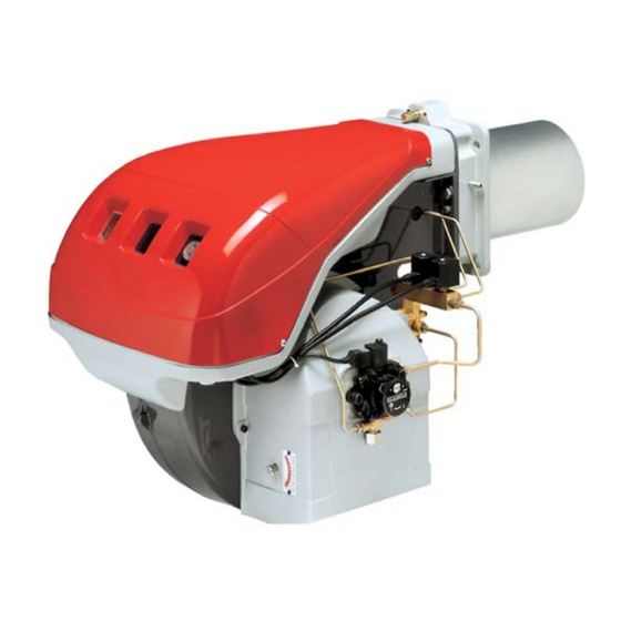
Page 5: Descrizione Bruciatore
(B). • Il peso del bruciatore completo di imballo è RL 70 1300 indicato nella tabella (B). RL 100 1300 RL 130 1300 INGOMBRO (C) - misure indicative L'ingombro del bruciatore è riportato in fig. (C). -
Page 6: Campi Di Lavoro
CAMPI DI LAVORO (A) I bruciatori RL 70-100-130 possono funzionare D687 in due modi: monostadio e bistadio. La PORTATA del 1° stadio va scelta entro l'area A dei diagrammi a lato. La PORTATA del 2° stadio va scelta entro l'area B (e C per RL 130). Quest' area fornisce la portata massima del bruciatore in funzione della pressione in camera di combustione. -
Page 7: Installazione
Forare la piastra di chiusura della camera di combustione come in (A). La posizione dei fori RL 70 275-325 M 12 filettati può essere tracciata utilizzando lo schermo termico a corredo del bruciatore. RL 100 275-325 M 12 RL 130 275-325 M 12 LUNGHEZZA BOCCAGLIO (B) -
Page 8: Montaggio Degli Ugelli
Esempio con RL 70 Potenza caldaia = 635 kW - rendimento 90 % Potenza richiesta al bruciatore = 635 : 0,9 = 705 kW 705 : 2 = 352 kW per ugello occorrono 2 ugelli uguali, 60°, 12 bar: 1° = 7,0 GPH - 2° = 7,0 GPH, oppure due ugelli differenti: 1°... -
Page 9: Impianto Idraulico
L (m) Legenda RL 70 RL 100 - 130 H = Dislivello pompa-valvola di fondo Ø (mm) Ø (mm) L = Lunghezza tubazione Ø = Diametro interno tubo... -
Page 10: Impianto Elettrico
IMPIANTO ELETTRICO RL 70 - RL 100 - RL 130 IMPIANTO ELETTRICO ESEGUITO IN FABBRICA IMPIANTO ELETTRICO eseguito in fabbrica SCHEMA (A) Bruciatori RL 70 - RL 100 - RL 130 • I modelli RL 70 - 100 - 130 lasciano la fabbri- ca previsti per alimentazione elettrica 400 V. - Page 11 COLLEGAMENTI ELETTRICI (A) RL 70 - RL 100 - RL 130 COLLEGAMENTI ELETTRICI eseguiti dall'installatore Usare cavi flessibili secondo norma EN 60 335-1: • se sotto guaina di PVC almeno tipo H05 VV-F • se sotto guaina di gomma almeno tipo H05 RR-F.
-
Page 12: Pompa
POMPA (A) POMPA SUNTEC E6 1 - Aspirazione G 1/4" 2 - Ritorno G 1/4" 3 - Attacco manometro G 1/8" 4 - Attacco vacuometro G 1/8" 5 - Regolazione di pressione 6 - Vite per by-pass A - Portata min. a 12 bar di pressione B - Campo di pressione in mandata C - Depressione max in aspirazione D - Campo di viscosità... -
Page 13: Regolazione Bruciatore
REGOLAZIONE BRUCIATORE REGOLAZIONE SERRANDA VENTILATORE ACCENSIONE Mettere l'interruttore 1)(C) posizione "ACCESO". Alla prima accensione, all'atto del passaggio dal 1° al 2° stadio, si ha un momentaneo abbassa- mento della pressione del combustibile conse- guente al riempimento della tubazione del 2° ugello. -
Page 14: Funzionamento Bruciatore
FUNZIONAMENTO BRUCIATORE AVVIAMENTO BRUCIATORE (A) - (B) Fasi di avviamento con tempi progressivi in secondi: • Chiusura telecomando TL. Dopo circa 3s: • 0 s : Inizia il programma dell’apparecchiatura elettrica. • 2 s : Avvio motore ventilatore. • 3 s : Inserimento trasformatore d’accensione. La pompa 3) aspira il combustibile dalla cis- terna attraverso il condotto 1) ed il filtro 2) e lo spinge sotto pressione in mandata. -
Page 15: Controlli Finali
CONTROLLI FINALI • Oscurare la fotoresistenza e chiudere i teleco- mandi: il bruciatore deve avviarsi e poi fer- marsi in blocco dopo circa 5 s dall'apertura della valvola di 1° stadio. • Illuminare la fotoresistenza e chiudere i teleco- mandi: il bruciatore deve avviarsi e, dopo circa 10 s, fermarsi in blocco. - Page 17 INDEX DONNÉES TECHNIQUES ......page 2 Modèles disponibles ........2 Accessoires .
-
Page 18: Données Techniques
DONNEES TECHNIQUES MODELE RL 70 RL 100 RL 130 TYPE 44992X 42761X - 58294X PUISSANCE 2e allure 474 - 830 711 - 1186 948 - 1540 Mcal/h 408 - 714 612 - 1020 816 - 1325 DEBIT kg/h 40 - 70... -
Page 19: Description Brûleur
(B). • Le poids du brûleur avec son emballage est in- diqué dans le tab. (B). RL 70 1300 ENCOMBREMENT (C) - mesures indicatives RL 100 1300 L'encombrement du brûleur est indiqué dans le RL 130 1300 tab. (C). -
Page 20: Plages De Puissance
PLAGES DE PUISSANCE (A) Les brûleurs RL 70 - 100 - 130 peuvent fonction- D687 ner en deux modes: à une allure et à deux allures. Le DEBIT de 1re allure doit être choisi dans la plage A des diagrammes ci-contre. Le DEBIT de 2éme allure doit être choisi dans la plage B (et C pour RL 130). -
Page 21: Installation
Percer la plaque de fermeture de la chambre de combustion comme sur la fig.(A). La position des RL 70 275-325 M 12 trous filetés peut être tracée en utilisant l'écran thermique du brûleur. RL 100 275-325 M 12 RL 130 275-325 M 12 LONGUEUR GUEULARD (B) La longueur de la buse doit être choisie selon les... -
Page 22: Montage Des Gicleurs
Exemple avec RL 70: Puissance chaudière = 635 kW rendement 90 % Puissance requise au brûleur = 635 : 0,9 = 705 kW; 705 : 2 = 352 kW par gicleur; Il faut 2 gicleurs identiques, 60°, 12 bar: 1er = 7,0 GPH - 2ème = 7,0 GPH, ou bien deux gicleurs différents: 1er = 6,0 GPH - 2ème = 8,0 GPH, ou bien:... -
Page 23: Installation Hydraulique
L (m) Légende RL 70 RL 100 - 130 H = Diff. niveau pompe-clapet de pied Ø (mm) Ø (mm) L = Longueur tuyau Ø... -
Page 24: Installation Électrique
INSTALLATION ELECTRIQUE RL 70 - RL 100 - RL 130 INSTALLATION ELECTRIQUE REALISEE USINE INSTALLATION ELECTRIQUE réalisée en usine SCHEMA (A) Brûleurs RL 70 - 100 - 130 • Les modèles RL 70 - 100 - 130 quittent l'usine prévus pour une alimentation électrique à... - Page 25 BRANCHEMENTS ELETRIQUESI (A) RL 70 - RL 100 - RL 130 BRANCHEMENTS ELECTRIQUES réalisée par l’installateur Utiliser câbles flexibles selon norme EN 60 335-1 • si en gaine PVC, au moins type H05 VV-F • si en gaine caoutchouc, au moins type H05 RR-F.
-
Page 26: Pompe
POMPE (A) POMPE SUNTEC E6 1 - Aspiration G 1/4" 2 - Retour G 1/4" 3 - Raccord manomètre G 1/8" 4 - Raccord vacuomètre G 1/8" 5 - Vis réglage pression 6 - Vis pour by-pass A - Débit min. a 12 bar de ression B - Plage de pression en refoulement C - Dépression max. -
Page 27: Réglage Brûleur
REGLAGE BRULEUR REGLAGE VOLET VENTILATEUR ALLUMAGE Mettre l'interrupteur 1)(C) sur la position "ALLU- ME". Au premier allumage ou au moment du passage de la 1re à la 2e allure, on a une baisse momen- tanée de la pression du combustible, liée au remplissage du conduit du 2e gicleur. -
Page 28: Fonctionnement Brûleur
FONCTIONNEMENT BRULEUR DEMARRAGE BRULEUR (A) - (B) Phases de démarrage avec temps progressifs en s.: • Fermeture télécommande TL. Après environ 3s: • 0 s : Le cycle de démarrage du coffret de sécurité est commencé. • 2 s : Démarrage moteur ventilateur. •... -
Page 29: Contrôles Finaux
CONTROLES FINAUX • Obscurcir la photorésistance et fermer les télé- commandes: le brûleur doit démarrer et se blo- quer 5 secondes environ après l’ouverture de la vanne de 1ère allure. • Eclairer la photorésistance et fermer les télé- commandes: le brûleur doit démarrer et, après environ 10 secondes, se bloquer. - Page 31 CONTENTS: TECHNICAL DATA ......page 2 Variants ..........2 Accessory.
-
Page 32: Technical Data
TECHNICAL DATA MODEL RL 70 RL 100 RL 130 TYPE 44992X 42761X - 58294X OUTPUT 2nd stage 474 - 830 711 - 1186 948 - 1540 Mcal/h 408 - 714 612 - 1020 816 - 1325 DELIVERY kg/h 40 - 70... -
Page 33: Burner Description
Outer dimensions of packaging are indicated in (B) RL 70 1300 • The weight of the burner complete with pack- RL 100 1300 aging is indicated in table (B). RL 130 1300 MAX. DIMENSIONS (C) -
Page 34: Firing Rates
FIRING RATES (A) The RL 70 - 100 - 130 Model burners can work in D687 two ways: one-stage and two-stage. 1st stage DELIVERY must be selected within area A of the adjacent diagrams. 2nd stage DELIVERY must be selected within area B (and C for model RL 130). -
Page 35: Installation
Drill the combustion chamber locking plate as RL 70 275-325 M 12 shown in (A). The position of the threaded holes can be marked using the thermal screen sup- RL 100 275-325 M 12 plied with the burner. RL 130 275-325... -
Page 36: Nozzle Assembly
Example with the RL 70 Model: Boiler output = 635 kW - efficiency 90 % Output required by the burner = 635 : 0,9 = 705 kW; 705 : 2 = 352 kW per nozzle; therefore, two equal, 60°, 12 bar nozzles are re- quired: 1°... -
Page 37: Hydraulic System
L (m) because the tank distance and/or height differ- ence are higher than the values listed in the table. RL 70 RL 100 - 130 Ø (mm) Ø (mm) Key (A) Pump/Foot valve height difference... -
Page 38: Electrical System
ELECTRICAL SYSTEM RL 70 - RL 100 - RL 130 ELECTRICAL EQUIPMENT FACTORY-SET ELECTRICAL SYSTEM factory set LAYOUT (A) Burners RL 70 - 100 - 130 • Models RL 70 - 100 - 130 leave the factory preset for 400 V power supply. - Page 39 ELECTRICAL CONNECTIONS (A) RL 70 - RL 100 - RL 130 ELECTRICAL CONNECTIONS set up by the installer Use flexible cables according to regulation EN 60 335-1: • if in PVC boot, use at least H05 VV-F • if in rubber boot, use at least H05 RR-F.
-
Page 40: Pump
PUMP (A) PUMP SUNTEC E6 1 - Suction G 1/4" 2 - Return G 1/4" 3 - Pressure gauge attachment G 1/8" 4 - Vacuum meter attachment G 1/8" 5 - Pressure adjustment screw 6 - Screw for by-pass A - Min. delivery rate at 12 bar pressure B - Delivery pressure range C - Max. -
Page 41: Burner Calibration
BURNER CALIBRATION FAN AIR GATE VALVE ADJUSTMENT FIRING Set switch 1)(C) to "ON". During the first firing, during the passage from the 1st to the 2nd stage, there is a momentary lowering of the fuel pressure caused by the filling of the 2nd stage nozzle tubing. -
Page 42: Burner Operation
BURNER OPERATION BURNER STARTING (A) - (B) Starting phases with progressive time intervals shown in seconds: • Control device TL closes. After about 3s: • 0 s : The control box starting cycle begins. • 2 s : The fan motor starts. •... -
Page 43: Final Checks
FINAL CHECKS • Obscure the photocell and switch on the con- trol devices: the burner should start and then lock-out about 5 s after opening of the 1st stage operation valve. • Illuminate the photocell and switch on the con- trol devices: the burner should start and then go into lock-out after about 10 s. - Page 44 RIELLO S.p.A. I-37045 Legnago (VR) Tel.: +39.0442.630111 http:// www.riello.it http:// www.rielloburners.com Con riserva di modifiche - Sous réserve de modifications - Subject to modifications...
Need help?
Do you have a question about the RL 100 and is the answer not in the manual?
Questions and answers