Table of Contents

Subscribe to Our Youtube Channel
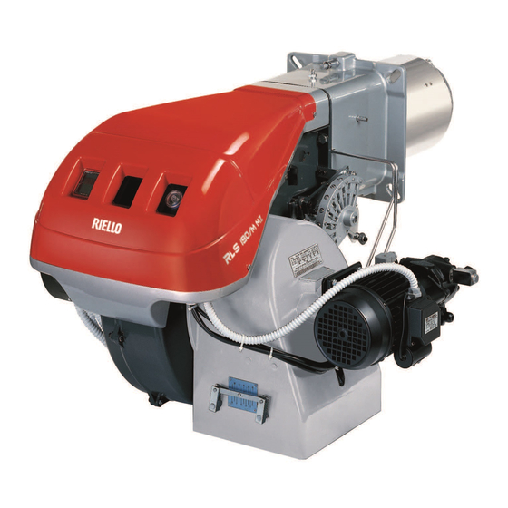
Related Manuals for Riello RLS 250/M


Summary of Contents for Riello RLS 250/M
- Page 1 Installation, use and maintenance instructions Dual fuel gas oil/ gas burner Two-stage progressive or modulating operation gas side / two-stage gas oil side CODE MODEL TYPE 20034278 RLS 250/M MZ 1302 T 20034293 (5) - 09/2013...
- Page 2 Original instructions...
- Page 3 Contents Declaration....................................3 Information and general warnings............................4 Information about the instruction manual ........................4 2.1.1 Introduction.................................. 4 2.1.2 General dangers................................4 2.1.3 Other symbols ................................4 2.1.4 Delivery of the system and the instruction manual...................... 5 Guarantee and responsibility............................5 Guidance for the use of bio fuel blends up to 10%......................
- Page 4 Contents 5.16.1 Gas train ..................................24 5.16.2 Gas train installation ..............................24 5.16.3 Gas pressure ................................24 5.17 Electrical wiring ................................25 5.17.1 Electrical connections ..............................25 5.18 Calibration of thermal relay ............................26 5.19 Current to the UV photocell............................26 Start-up, calibration and operation of the burner ........................27 Notes on safety for the first start-up ...........................27 Adjustment before first firing (gas oil operation) ......................27 6.2.1...
-
Page 5: Declaration
The quality is guaranteed by a quality and management system certified in accordance with UNI EN ISO 9001. Manufacturer's Declaration RIELLO S.p.A. declares that the following products comply with the NOx emission limits specified by German standard “1. BImSchV release 26.01.2010”. -
Page 6: Information And General Warnings
Information and general warnings Information and general warnings Information about the instruction manual 2.1.1 Introduction WARNING: MOVING PARTS The instruction manual supplied with the burner: This symbol indicates that you must keep limbs is an integral and essential part of the product and must not away from moving mechanical parts;... -
Page 7: Delivery Of The System And The Instruction Manual
All components within the hydraulic circuit suitable for burner is integral and complete. bio fuel use and supplied by Riello will be identified as Bio com- patible. No warranty is given in relation to the use of components Failure to observe the information given in this which are not so identified with bio fuel blends. -
Page 8: Guidance For The Use Of Bio Fuel Blends Up To 10
To ensure consistency, the supplier of the fuel must be able to In no event shall Riello (and its subsidiaries) be liable for any in- demonstrate compliance with a recognised Quality Control and... -
Page 9: Safety And Prevention
Safety and prevention Safety and prevention Introduction The burners have been designed and built in compliance with the type and pressure of the fuel, the voltage and frequency of the current regulations and directives, applying the known technical electrical power supply, the minimum and maximum deliveries for rules of safety and envisaging all the potential danger situations. -
Page 10: Technical Description Of The Burner
3 / 220V / 60Hz - 3N / 380V / 60Hz Auxiliary voltage : 230/50/60 230V / 50-60Hz 110/50/60 110V / 50-60Hz 3/230-400/50 230/50 BASIC DESIGNATION EXTENDED DESIGNATION Models available Designation Electrical supply Code RLS 250/M MX 3/230-400/50 20034278 Tab. A 20034293... -
Page 11: Countries Of Destination - Burner Categories
II 2ELL3B/P I 2E(R)B, I 3P II 2E3B/P I 3B/P NO - CY - MT I 2H Tab. B Technical data Model RLS 250/M MZ Type 1302 T Output stage 1230 - 2460 Delivery kg/h 104 - 207 min. 1... -
Page 12: Electrical Data
Technical description of the burner Electrical data Motor IE1 Model RLS 250/M MZ Electrical supply V/Ph/Hz 400/3/50 Auxiliary power supply V/Ph/Hz 230/1N/50 Fan motor 2900 230 / 400 5500 Running current 21.6 - 12.5 Start-up current 144 - 83 Pump motor... -
Page 13: Overall Dimensions
I. Bear in mind that inspection of the combustion head requires the burner to be opened and the rear part withdrawn on the slide bars. D3169 Fig. 2 RLS 250/M MZ 412-542 1442-1587 Tab. G Blast tube: short-long Firing rate During operation, burner output varies between: The firing rate value (Fig. -
Page 14: Test Boiler
Technical description of the burner Test boiler The firing rate was set in relation to special test boilers, according to EN 676 regulations. Fig. 4 indicates the diameter and length of the test combustion chamber. D715 Example: output 650 Mcal/h: diameter = 60 cm; length = 2 m. 4.9.1 Commercial boilers The burner is suitable for operation on boilers with combustion... -
Page 15: Burner Description
1 - Spare parts list In case of use with gas oil containing up to 10% Bio blend, it will be essential to use flexible oil lines suitable for bio fuel use. Please contact Riello for further information. WARNING 20034293... -
Page 16: Installation
Installation Installation Notes on safety for the installation After carefully cleaning all around the area where the burner will The installation of the burner must be carried out be installed, and arranging the correct lighting of the environ- by qualified personnel, as indicated in this manual ment, proceed with the installation operations. -
Page 17: Installer/Servicer Notes For The Use Of Gas Oil With Bio Blends Up To 10
The burner hydraulic components and flexible oil lines must burner technical manual). be suitable for bio fuel use (check with Riello if in doubt). If a Bio blend is in use the installer must seek information Riello have carefully chosen the specification of the bio... -
Page 18: Blast Tube Length
Riello S.p.A. and inadequate regular maintenance In order to guarantee that emissions do not vary, recommended may result into emission limits non-conforming to and/or alternative nozzles specified by Riello in the Instruction the values set forth by the regulations in force, and CAUTION and warning booklet should be used. -
Page 19: Nozzle Assembly
Installation 5.8.1 Choice of nozzles for 1 and 2 stage Both nozzles must be chosen from among those listed in Tab. J. The first nozzle determines the delivery of the burner in the 1st stage. The second nozzle works together with the 1st nozzle to deter- mine the delivery of the burner in the 2nd stage. -
Page 20: Electrode Position
Installation Electrode position Make sure that the electrodes are positioned as shown in Fig. 14. WARNING D2995 Fig. 14 5.10 Burner closing Refit the burner to the slide bars 3)(Fig. 15) at approximately 100 mm from the sleeve 4) - burner positioned as shown in Fig. -
Page 21: Gas Oil Supply
DANGER You are advised to use additional filters on the fuel supply line. Riello recommends a good quality fuel filter at the tank (Fig. 17 - Fig. 18) and a secondary filter CAUTION (100 for gas oil and 15 for kerosene) are used to protect the burner pump and nozzle from con- tamination. -
Page 22: Single-Pipe Circuit
Installation 5.12.3 Single-pipe circuit In order to obtain single-pipe working it is necessary to unscrew the return hose, remove the by-pass screw 6)(Fig. 19) and then screw the plug 7)(Fig. 19). The distance “P” must not exceed 10 meters in order to avoid subjecting the pump's seal to excessive strain;... -
Page 23: Hydraulic Connections
Pump In case of use with gas oil containing up to 10% Bio blend, it will be essential to use flexible oil lines suitable for bio fuel use. Please contact Riello for further information. WARNING Technical data D1251 Suntec E7CC Min. - Page 24 Installation Pump priming Before starting the burner, make sure that the tank return line is not clogged. Obstructions in the line could cause the seal- WARNING ing organ located on the pump shaft to break. (The pump leaves the factory with the by-pass D791 closed).
-
Page 25: Gas Feeding Line
Installation 5.16 Gas feeding line Explosion danger due to fuel leaks in the pres- ence of a flammable source. Precautions: avoid knocking, attrition, sparks and heat. Make sure that the fuel interception tap is closed before performing any operation on the burner. The fuel supply line must be installed by qualified personnel, in compliance with current standards and laws. -
Page 26: Gas Train
Installation Column 1 5.16.1 Gas train Pressure loss at combustion head. It is type-approved according to EN 676 Standards and is sup- Gas pressure measured at test point 1)(Fig. 25), with: plied separately from the burner. – combustion chamber at 0 mbar; To select the correct gas train model, refer to the supplied "Burn- –... -
Page 27: Electrical Wiring
Do not touch the device with wet or damp body parts and/or in bare feet. Do not pull the electric cables. Before carrying out any maintenance, cleaning or checking oper- Riello S.p.A. declines all liability for modifications ations: or connections other than those shown on these diagrams. -
Page 28: Calibration Of Thermal Relay
Installation 5.18 Calibration of thermal relay The thermal relay (Fig. 27) is used to avoid damage to the motor owing to a strong increase in absorption or the lack of a phase. For the calibration 2), refer to the table given in electrical layout (Electrical connections set by installer). -
Page 29: Start-Up, Calibration And Operation Of The Burner
Start-up, calibration and operation of the burner Start-up, calibration and operation of the burner Notes on safety for the first start-up The first start-up of the burner must be carried out Check the correct working of the adjustment, com- by qualified personnel, as indicated in this manual mand and safety devices. -
Page 30: Operation
Start-up, calibration and operation of the burner 6.3.2 Operation Pump pressure 12 bar: this is the pressure calibrated in the factory which is The optimum calibration of the burner requires an analysis of the usually sufficient for most purposes. flue gases at the boiler outlet and interventions on the following Sometimes, this pressure must be adjusted to: points. -
Page 31: Burner Starting (Gas Operation)
Start-up, calibration and operation of the burner Burner starting (gas operation) age is present. If voltage is present, then immediately stop the It is advisable to first set the burner for operating burner and check electrical connections. on oil and then for gas. Execute the fuel exchange when the burner is off. -
Page 32: Min Burner Output
Start-up, calibration and operation of the burner D1710 D3924 Fig. 38 Fig. 37 Key Fig. 37 Adjustment of air delivery Progressively adjust the starting profile of cam 4)(Fig. 37) by turn- Servomotor Servomotor 1) - Cam 4): engaged ing the screws 5). Servomotor 1) - Cam 4): disengaged It is preferable not to turn the first screw since this is used to set Adjustable profile cam... -
Page 33: Pressure Switch Adjustment
Start-up, calibration and operation of the burner Pressure switch adjustment 6.8.1 Air pressure switch Adjust the air pressure switch after having performed all other burner adjustments with the air pressure switch set to the start of the scale (Fig. 39). With the burner working at MIN output, insert a combustion ana- lyser in the stack, slowly close the suction inlet of the fan (for ex- ample, with cardboard) until the CO value does not exceed 100... -
Page 34: Combustion Checks
Start-up, calibration and operation of the burner Combustion checks It is better to set the burner with CO not higer than 10% (gas with It must be not higher than 100 mg/kWh. Pci 8,600 kcal/m In this way avoiding a loss of calibration setting (for example draft variation) that could cause combustion with little air and the pro- duction of CO. -
Page 35: Maintenance
Maintenance Maintenance Notes on safety for the maintenance The periodic maintenance is essential for the good operation, safety, yield and duration of the burner. Disconnect the electrical supply from the burner It allows you to reduce consumption and polluting emissions and by means of the main system switch. - Page 36 Maintenance Combustion GAS OIL OPERATION In case the combustion values found at the beginning of the inter- vention do not respect the standards in force or, in any case, do Filters not correspond to a proper combustion, contact the Technical Check the filtering baskets on line and at nozzle present in the Assistant and have him carry out the necessary adjustments.
-
Page 37: Opening The Burner
Maintenance Opening the burner Loosen screws 1)(Fig. 45) and withdraw the cover 2). Disconnect the light-oil pipes 7). Disconnect the electrical supply from the burner Disengage the articulated coupling 8) from the graduated by means of the main system switch. sector 9). -
Page 38: Faults - Possible Causes - Solutions
Faults - Possible causes - Solutions Faults - Possible causes - Solutions Find a list of faults, causes and possible solutions for a set of fail- In the event of a burner lockout, more than two ures that may occur and result in irregular burner operation or no consecutive burner reset operations could cause functioning at all. - Page 39 Faults - Possible causes - Solutions GAS OIL OPERATION SYMBOL FAULT PROBABLE CAUSE SUGGESTED REMEDY After pre-purge and the safety The solenoid VP1 allows little gas through Increase time, the burner goes to lock- Solenoid valves VP1 or VP2 fail to open Renew the coil or rectifier panel out and the flame does not No fuel in tank;...
- Page 40 Faults - Possible causes - Solutions GAS OIL OPERATION SYMBOL FAULT PROBABLE CAUSE SUGGESTED REMEDY Pump unprimes after pro- Bring to same height as suction Return pipe not immersed in fuel longed pause pipe Air enters suction piping Tighten connectors Pump leaks gas oil Leakage from sealing organ Replace pump...
- Page 41 Faults - Possible causes - Solutions GAS OPERATION SYMBOL FAULT PROBABLE CAUSE SUGGESTED REMEDY The burner does not start Close all switches and check con- No electrical power supply nections A limiter or safety control device is open Adjust or replace Control box lock-out Reset control box Control box fuse blown...
- Page 42 Faults - Possible causes - Solutions GAS OPERATION SYMBOL FAULT PROBABLE CAUSE SUGGESTED REMEDY The burner repeats the start- Mains gas pressure is near the valve to which the ing cycle without lock out min. gas pressure switch gas is adjusted. The repeated drop in pressure which follows valve opening causes temporary opening of the Reduce operating pressure of...
-
Page 43: A Appendix - Accessories (Optional)
Degassing units are provided in two versions: If burner head penetration into the combustion chamber needs Burner Code reducing, varying thickness spacers are available, as given in the following table. RLS 250/M MZ (without filter) 20034277 RLS 250/M MZ (with filter) 20034281 Burner Code... -
Page 44: B Appendix - Electrical Panel Layout
Appendix - Electrical panel layout Appendix - Electrical panel layout Index of layouts References layout LFL 1... Operational layout LFL 1... Operational layout LFL 1... Operational layout Electrical connections set by installer RWF40 ... Operational layout Reference layout / 1 . A 1 Sheet no. - Page 45 Appendix - Electrical panel layout 20034293...
- Page 46 Appendix - Electrical panel layout 20034293...
- Page 47 Appendix - Electrical panel layout 20034293...
- Page 48 Appendix - Electrical panel layout 20034293...
- Page 49 Appendix - Electrical panel layout 20034293...
- Page 50 Appendix - Electrical panel layout 6 pin plug Key to lay-out Control box 4 pin plug Protection against radio interference External components Output power regulator RWF40 Fuses for three-phase line protection DC input 4...20 mA Fuses for auxiliary line protection DC input 4...20 mA for modifying the remote setpoint Burners components Boiler components...
- Page 52 RIELLO S.p.A. I-37045 Legnago (VR) Tel.: +39.0442.630111 http:// www.riello.it http:// www.rielloburners.com Subject to modifications...
Need help?
Do you have a question about the RLS 250/M and is the answer not in the manual?
Questions and answers