Moxa Technologies V2406 Hardware Manual
Hide thumbs
Also See for V2406:
- Quick installation manual (2 pages) ,
- Quick installation manual (2 pages)
Table of Contents
Advertisement
Quick Links
:
mxk@nt-rt.ru
||
www.moxa.nt-rt.ru
: +7(7172)727-132
: (8182)63-90-72
: (4722)40-23-64
: (4832)59-03-52
:
(423)249-28-31
: (844)278-03-48
: (8172)26-41-59
: (473)204-51-73
: (343)384-55-89
: (4932)77-34-06
: (3412)26-03-58
: (843)206-01-48
: (4012)72-03-81
:
(4842)92-23-67
: (3842)65-04-62
: (8332)68-02-04
: (861)203-40-90
: (391)204-63-61
: (4712)77-13-04
: (4742)52-20-81
: (3519)55-03-13
(495)268-04-70
:
(8152)59-64-93
: (8552)20-53-41
: (831)429-08-12
: (3843)20-46-81
: (383)227-86-73
: (4862)44-53-42
: (3532)37-68-04
: (8412)22-31-16
: (342)205-81-47
-
-
: (863)308-18-15
: (4912)46-61-64
: (846)206-03-16
-
: (812)309-46-40
:
(845)249-38-78
: (4812)29-41-54
: (862)225-72-31
: (8652)20-65-13
: (4822)63-31-35
:
(3822)98-41-53
: (4872)74-02-29
: (3452)66-21-18
: (8422)24-23-59
(347)229-48-12
: (351)202-03-61
: (8202)49-02-64
: (4852) 69-52-93
V2406/2422/2426 Hardware Manual
Advertisement
Table of Contents

Related Manuals for Moxa Technologies V2406


Summary of Contents for Moxa Technologies V2406
- Page 1 : (3532)37-68-04 : (8412)22-31-16 : (342)205-81-47 : (863)308-18-15 : (4912)46-61-64 : (846)206-03-16 : (812)309-46-40 (845)249-38-78 : (4812)29-41-54 : (862)225-72-31 : (8652)20-65-13 : (4822)63-31-35 (3822)98-41-53 : (4872)74-02-29 : (3452)66-21-18 : (8422)24-23-59 (347)229-48-12 : (351)202-03-61 : (8202)49-02-64 : (4852) 69-52-93 V2406/2422/2426 Hardware Manual...
- Page 2 V2406/2422/2426 Hardware Manual The software described in this manual is furnished under a license agreement and may be used only in accordance with the terms of that agreement. Copyright Notice © 2014 Moxa Inc., All rights reserved. Trademarks The MOXA logo is a registered trademark of Moxa Inc.
-
Page 3: Table Of Contents
Table of Contents Introduction ............................1-1 Overview ............................1-2 Package Checklist ..........................1-2 Product Features ..........................1-2 V2406/2422/2426 Hardware Specifications .................... 1-3 Hardware Block Diagram ........................1-5 Hardware Introduction........................2-1 Appearance ............................2-2 V2406 ............................2-2 V2422 ............................2-2 V2426 ............................2-3 Dimensions ............................ - Page 4 Load System Default Settings ..................... 4-11 Load System Turbo Settings ....................... 4-11 Load CMOS from BIOS ....................... 4-11 Save CMOS to BIOS ........................4-11 Exiting the BIOS Setup ........................4-12 Save & Exit Setup ........................4-12 Exit Without Saving ........................4-12 Upgrading the BIOS ..........................
-
Page 5: Introduction
Introduction The V2406/2422/2426 embedded computers are based on the Intel Atom N270 x86 processor, and feature four RS-232/422/485 serial ports, dual 10/100 Mbps (10/100/1000 Mbps for V2422) LAN ports, 3 USB 2.0 hosts (6 for V2422), and a CompactFlash socket. The V2406/2422/2426 computers provide VGA, DVI-I outputs, and digital input/output channels, making them particularly well-suited for industrial applications such as SCADA and manufacturing automation. -
Page 6: Overview
The V2406/2422/2426 computers come with 4 RS-232/422/485 serial ports, making them ideal for connecting a wide range of serial devices, and the dual 10/100 Mbps Ethernet ports for the V2406/2426 (dual 10/100/1000 Mbps Ethernet ports for the V2422) offer a reliable solution for network redundancy, promising continuous operation for data communication and management. -
Page 7: V2406/2422/2426 Hardware Specifications
System Memory: 2 GB capacity, 1 GB (LX and XPE models)/2 GB (W7E models) pre-installed: 1 slot of 200 pin DDR2-533 SO-DIMM SDRAM USB: • V2406/2426:3 bootable USB 2.0 ports: 2 type A, 1 M12 • V2422: 6 bootable USB 2.0, type A Storage... - Page 8 • V2422/2426: 4 kg Dimensions: Without ears: • V2406:250 x 57 x 154 mm (9.84 x 2.24 x 6.06 in) • V2422/2426: 250 x 86 x 154 mm (9.84 x 3.39 x 6.06 in) With ears: V2406: 275 x 63 x 154 mm (10.83 x 2.48 x 6.06 in) V2422/2426: 275 x 92 x 154 mm (10.83 x 2.48 x 3.62 in)
-
Page 9: Hardware Block Diagram
Green Product: RoHS, CRoHS, WEEE Reliability Automatic Reboot Trigger: Software-programmable watchdog timer configurable from 1 to 255 seconds MTBF (mean time between failures): • V2406: 230,723 hrs • V2422: 144,114 hrs • V2426: 192,308 hrs Warranty Warranty Period: 3 years Details: See www.moxa.com/warranty... -
Page 10: Hardware Introduction
Hardware Introduction The V2406/2422/2426 series embedded computers are compact, well-designed, and built rugged enough for industrial applications. LED indicators help you monitor performance and identify trouble spots, multiple serial ports allow you to connect different devices for wireless operation, and the reliable and stable hardware platform lets you devote your attention to developing your applications. -
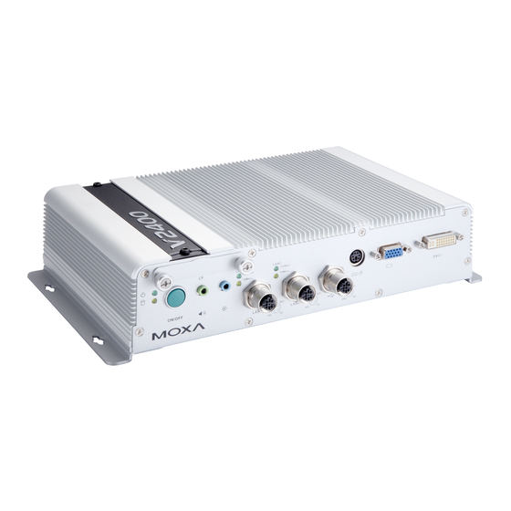
Page 11: Appearance
V2406/2422/2426 Hardware Manual Hardware Introduction Appearance V2406 Front View Rear View V2422 Front View... -
Page 12: V2426
V2406/2422/2426 Hardware Manual Hardware Introduction Rear View V2426 Front View Rear View... -
Page 13: Dimensions
V2406/2422/2426 Hardware Manual Hardware Introduction Dimensions V2406 V2422... -
Page 14: V2426
Reset Button Press the Reset Button on the rear panel of the V2406/2422/2426 to reboot the system automatically. The Ready LED will blink on and off for the first 5 seconds, and then maintain a steady glow once the system has rebooted. - Page 15 V2406/2422/2426 Hardware Manual Hardware Introduction ATTENTION There is a risk of explosion if the wrong type of battery is used. To avoid this potential danger, always be sure to use the correct type of battery. Dispose of used batteries according to the instructions on the battery.
-
Page 16: Hardware Connection Description
Hardware Connection Description In this chapter, we show how to connect the embedded computers to the network and to various devices. The following topics are covered in this chapter: Installing the V2406/2422/2426 Wiring Requirements Connecting the Power ... -
Page 17: Installing The V2406/2422/2426
Wall or Cabinet Mounting The V2406/2422/2426 comes with two metal brackets for attaching it to a wall or the inside of a cabinet. Step 1: Use two screws for each bracket and attach the bracket to the rear of the V2406/2422/2426. - Page 18 Hardware Connection Description To attach the DIN-rail kit, turn the V2406/2422/2426 over to the bottom cover. Find the locations for the screws and place the brackets on the cover. Please note that all eight screws must be firmly attached so that the computer can be securely installed on the DIN-rail.
-
Page 19: Wiring Requirements
It is advisable to label the wiring to all devices in the system. ATTENTION Safety First! Be sure to disconnect the power cord before installing and/or wiring your V2406/2422/2426. Wiring Caution! Calculate the maximum possible current in each power wire and common wire. Observe all electrical codes dictating the maximum current allowable for each wire size. -
Page 20: Connecting Data Transmission Cables
V2406/2422/2426 Hardware Manual Hardware Connection Description Connecting Data Transmission Cables This section describes how to connect the V2406/2422/2426 embedded computers to the network and serial devices. Connecting to the Network V2406/2426 Plug your network cable into the embedded computer’s Ethernet port. The other end of the cable should be plugged into your Ethernet network. -
Page 21: Installing A Compactflash Card
4. Gently insert the CompactFlash card into the CF socket, making sure that the card is oriented correctly. ATTENTION The V2406/2422/2426 embedded computer does not support the CompactFlash hot swap and PnP (Plug and Play) functions. It is necessary to remove power source first before inserting or removing the CompactFlash... -
Page 22: Connecting A Ps/2 Keyboard And Mouse
Connecting to a USB Device The V2406/2426 comes with 1 USB 2.0 host with M12 connectors on the front panel, and 2 USB 2.0 hosts with type A connector on the rear panel; the V2422 comes with 4 USB 2.0 hosts on the front panel and 2 USB 2.0 hosts on the rear panel, all with type A connector. -
Page 23: V2406
V2406/2422/2426 Hardware Manual Hardware Connection Description V2406 V2426 Refer to the following figure for the pin assignment of the USB host with M12 connector. -
Page 24: V2422
V2422 DI/DO The V2406/2426 comes with a 6-ch digital input and a 2-ch digital output through a terminal block connector, and the V2422 comes with a 4-ch digital input and a 4-ch digital output through a terminal block connector. The pin assignments and the wiring methods are shown below. -
Page 25: V2422
Connecting to a VGA Monitor The V2406/2422/2426 comes with a D-Sub 15-pin female connector on the front panel to connect a VGA CRT monitor. To ensure that the monitor image remains clear, be sure to tighten the monitor cable after connecting it to the V2406/2422/2426. -
Page 26: Connecting To A Dvi-I Monitor
Connecting to a DVI-I Monitor The V2406/2422/2426 computers also come with a DVI-I connector that can connect to a DVI monitor. Use the cable to connect one end to the DVI-I connector and the other end to the monitor. See the following table for DVI-I connector pin assignments. -
Page 27: Inserting Expansion Modules
V2406/2422/2426 Hardware Manual Hardware Connection Description Inserting Expansion Modules The V2422 and V2426 computers come with 2 peripheral expansion slots for inserting different communication modules, such as a 2-port CAN module, an HSDPA, GPS, WLAN module, an 8+8 port digital input/output module, a 2-port serial module, a mini PCI expansion module, or a PCI Express module, providing greater flexibility for setting up different industrial applications at field sites. -
Page 28: Upgrading The Memory Module
1. Disconnect the V2406/2422/2426 from the power source. 2. We suggest placing the V2406/2422/2426 upside down and then removing all the screws on the front and rear panels. Remember to remove all screws from the DB9 connectors and the terminal blocks for digital input/output and the power. - Page 29 4. Push back the bottom cover of the V2422/2426 computer; you will be able to see the memory module socket on the main board. 5. For the V2406, simply push back the bottom cover to see the location of the memory module socket on the main board.
-
Page 30: Upgrading The Dom Module
1. After taking off the back cover of the V2406/2422/2426, find the location of the DOM module socket. 2. Pull up and take off the DOM module, and then place the new DOM module into the slot. - Page 31 V2406/2422/2426 Hardware Manual Hardware Connection Description 3. Unpack the HDD bracket package. This package is not included in the product, and should be purchased separately. Check the items in the following figure: The HDD package includes an HDD bracket, four HDD screws, for damping materials, four bronze screws, one SATA power cable and one SATA cable.
- Page 32 7. Place the HDD bracket onto the mainboard of the computer, and then fasten the bracket with the screws. 8. Connect the SATA power cable and the SATA cable to the connectors. 9. Replace the back cover of the V2406/2422/2426 computer to finish the installation. 3-17...
-
Page 33: Adjusting Com1 Pin 9 Voltage
Adjusting COM1 PIN 9 Voltage PIN 9 of the V2406/2422/2426’s serial port 1 can be set to 0 V, +5 V, or +12 V by jumper. The jumper is located between the serial port and the memory module on the mainboard. -
Page 34: Bios Setup
BIOS Setup This chapter describes the BIOS settings of the V2406/2422/2426 embedded computers. The BIOS is a set of input/output control routines for peripherals. The BIOS is used to initialize basic peripherals and helps boot the operating system before the operating system is loaded. The BIOS setup allows the user to modify the system configurations of these basic input/output peripherals. -
Page 35: Entering The Bios Setup Utility
V2406/2422/2426 Hardware Manual BIOS Setup Entering the BIOS Setup Utility To enter the BIOS setup utility, press the “Del” key while the system is booting up. The main BIOS Setup screen will appear. A basic description of each function key is listed at the bottom of the screen. Refer to these descriptions to learn how to scroll about the screen, how to select by pressing “Enter,”... -
Page 36: System Security
V2406/2422/2426 Hardware Manual BIOS Setup System Security To set up system security, select the “Security” option under “Main” to bring up the following screen. This menu includes two options: “Set Password” and “Security Option.” When you select the Set Password option, a pop-up “Enter Password:” window will appear on the screen. The password that you type will replace the password stored in the CMOS memory. -
Page 37: Hard Disk Boot Priority
V2406/2422/2426 Hardware Manual BIOS Setup Hard Disk Boot Priority First/Second/Third Boot Device This option allows users to select or change the device boot priority. You may set 3 levels of priority to determine the boot up sequence for different bootable devices, such as a hard drive, CD-ROM, and removable devices. -
Page 38: Advanced Chipset Settings
V2406/2422/2426 Hardware Manual BIOS Setup Hyper-Threading Technology This item allows you to enable or disable the hyper-threading function, which allows the system to handle more than one thread at the same time. Options: Enabled (default), Disabled Quick Power On Self Test This setting allows the system to skip certain tests while the system boots up. -
Page 39: Peripherals
V2406/2422/2426 Hardware Manual BIOS Setup DVMT/FIXED Memory Size This item sets the maximum amount of system memory that can be allocated as graphics memory. Options: 64 MB, 128 MB (default). Boot Display This item allows you to choose which display interface will be shown when system is booting up. Due to the display limitation, two displays at most can be shown when booting up. -
Page 40: Onboard Device
V2406/2422/2426 Hardware Manual BIOS Setup On-Chip Channel 0 PCI IDE This item allows you to enable or disable the Channel 0 onboard PCI device. Options: Enabled (default), Disabled IDE Channel 0 Master UDMA This item allows you to configure UDMA mode for the device on IDE channel 0 Master. -
Page 41: Super I/O Device
Super I/O Device Debug Port This function allows you to enable/disable the debug port communication. The V2406/2422/2426 computer will automatically distribute the IRQ value for the debug port as the default value. If you wish to disable, select Disabled. This port is only for engineers who are debugging programs. -
Page 42: Do Setting
V2406/2422/2426 Hardware Manual BIOS Setup DO Setting This item allows users to configure the V2406/2426’s DO states. 1 refers to high (open) while 0 refers to low (ground). Option: 1 (default), 0 Note: For the V2422, four DO settings can be configured. -
Page 43: Power
V2406/2422/2426 Hardware Manual BIOS Setup Power The Power Setup Menu allows you to configure your system power-up/ power-down options. ACPI Suspend Type This item allows you to set up the ACPI suspend type for power management function. Option: S1 (POS), (default), S3 (STR) Soft-Off by PWR-BTTN This item determines the delay to stop the software when pushing the power button. -
Page 44: Cpu Warning Temperature
V2406/2422/2426 Hardware Manual BIOS Setup CPU Warning Temperature This item allows you to configure what temperature will trigger a high temperature warning. Options: 80°C/176°F, 90°C/194°F (default), 100°C/212°F, Disabled Warning Beep This item allows you to enable/disable the warning beep. Options: Disabled (default), Enabled... -
Page 45: Exiting The Bios Setup
V2406/2422/2426 Hardware Manual BIOS Setup Exiting the BIOS Setup To exit the BIOS setup utility, choose “Exit.” Pressing <ESC> will achieve the same result. Save & Exit Setup Save all configuration changes to CMOS (memory) and exit setup. A confirmation message will be displayed before proceeding. - Page 46 V2406/2422/2426 Hardware Manual BIOS Setup ATTENTION We suggest you use a USB drive with under 2 GB in disk space, as larger USB drives may not support FAT file format and consequently fail to boot. Step 2: Prepare the Upgrade Tool and BIOS Binary File.
- Page 47 V2406/2422/2426 Hardware Manual BIOS Setup 5. Press “+” to move it up to the first priority, and press “Esc” to exit the setup menu. 6. Make sure the first boot device is Hard Disk. If it isn’t, press Enter to change it.
-
Page 48: Regulatory Approval Statement
Regulatory Approval Statement This device complies with part 15 of the FCC Rules. Operation is subject to the following two conditions: (1) This device may not cause harmful interference, and (2) this device must accept any interference received, including interference that may cause undesired operation.
Need help?
Do you have a question about the V2406 and is the answer not in the manual?
Questions and answers