Table of Contents
Advertisement
Available languages
Available languages
Quick Links
Advertisement
Chapters
Table of Contents

Related Manuals for Megasat Satmaster Portable


Summary of Contents for Megasat Satmaster Portable
- Page 1 Satmaster Portable Bedienungsanleitung...
-
Page 2: Table Of Contents
Inhaltsverzeichnis 1. Einführung 1.1 Allgemeine Informationen ..............03 1.2 Auspacken ..................... 03 1.3 Lieferumfang ....................03 2. Bezeichnungen 2.1 Bezeichnungen der Außeneinheit ..........04 2.2 Bezeichnungen der Bedienfelder ............ 04 2.3 Bezeichnungen der Stromeinspeisung ........05 2.4 Bezeichnungen des Steuergerätes..........05 3. -
Page 3: Einführung
Einführung 1.1 Allgemeine Informationen Bitte lesen Sie die Bedienungsanleitung sorgfältig vor Inbetriebnahme des Gerätes. Bei falscher oder unsachgemäßer Handhabung erlischt der Gewährleistungsanspruch. Hinweis: Falls Sie schon ähnliche Produkte installiert haben, muss die Vorge- hensweise mit diesem Produkt nicht zwingend übereinstimmen. 1.2 Auspacken Hinweis: Fassen Sie die Antenne nie am Spiegel, sonden nur am Gehäuse an! RICHTIG! -
Page 4: Bezeichnungen
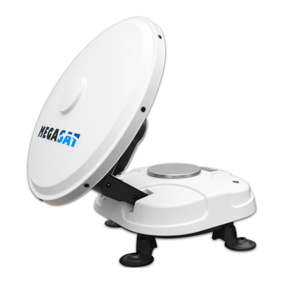
2. Bezeichnungen 2.1 Bezeichnungen der Außeneinheit Polarisationsskala (Skew) Spiegel Oberer Endschalter LNB Abdeckung Kompass Gummifuß Metallöse zur Diebstahlsicherung Bedienfeld (nur bei der Premium Version) 2.2 Bezeichnungen der Bedienfelder Classic Premium Professional keine „Hoch“ Taste „Set“ Taste keine Funktion zur Auswahl zur Bestätigung Funktion „Runter“... -
Page 5: Bezeichnungen Der Stromeinspeisung
2. Bezeichnungen 2.3 Bezeichnungen der Stromeinspeisung (Classic und Premium Version) Antennenanschluss Receiveranschluss Betriebsanzeige LED DC Stromanschluss Ein / Aus Schalter 2.4 Bezeichnungen des Steuergerätes (Professional Version) LCD Display Netzschalter DOWN „Hoch“ Taste „Runter“ Taste Bestätigungstaste SETTOP DATA DC12-24 V Anschluss Anschluss Anschluss Stromversorgung... -
Page 6: Installation
3. Installation 3.1 Wahl des Standortes Um ein Satellitensignal zu empfangen, muss die Antenne stets im Freien installiert und grob Richtung Süden ausgerichtet werden. Nutzen Sie zur groben Einstellung den inte- grierten Kompass am Gerät (Richten Sie sich nach den Azimuthwerten in der Tabelle am Ende des Handbuches). -
Page 7: Anschluss Der Antenneneinheit
3. Installation 3.2 Anschluss der Antenneneinheit Außenbereich Classic und Premium Version SETTOP Receiver 24 Volt 12/24 Volt Einspeisekabel Fernseher Spannungs- Einspeisekabel wandler 1. Antennenposition Platzieren Sie die Antenne mit freier Sicht Professional Version zum Satelliten. Die Antenne kann auf jedem stabilen Platz mit geradem Untergrund platziert werden. -
Page 8: Inbetriebnahme
Sie alle Verbindungen und Einstellungen (Receiver, Satmaster Portable und TV) und folgen den obi- gen Schritten noch einmal. Wenn Sie die Nutzung des Satmaster Portable beenden oder die Antenne zum Transport in die Parkposition brin- gen möchten, schalten Sie die Antenne an der Stromeinspeisung, bzw. am Steuergerät wieder ein und warten bis die Antenne in die Parkposition gefahren ist. -
Page 9: Anzeigen Des Lcd Displays
3. Installation 3.4 Anzeigen des LCD Displays Das LCD Display zeigt den aktuellen Status des automatischen Suchsystems. (nur bei Satmaster Portable Premium und Professional) ASTRA1 Beispiel Satellitenauswahl 19.2E EL 30DEG Beispiel Elevationsauswahl SIGNAL Satellitensignal gefunden DETECTED Bestätigt, dass das Signal des Zielsatelliten richitg ist DETECTED Kann kein Satellitensignal finden. -
Page 10: Beispiele Für Das Auffinden Des Satelliten
3. Installation 3.5 Beispiel für das Auffinden des Satelliten Polarisationswinkel (Skew): Stellen Sie den entsprechenden Polarisationswinkel ein. Nutzen Sie hierzu die Skala auf der Rückseite der Antenne. Den entsprechenden Polarisationswinkel des jeweiligen Satelliten finden Sie in der Tabelle auf Seite 12. Elevation: Passen Sie den Elevationswinkel entsprechend der Tabelle auf Seite 12 an. - Page 11 3. Installation Satellitenposition Azimuth (Drehung) Alle EU-relevanten 158° vom Satelliten liegen im Süden. geographischen Nordpol Satmaster Portable Elevation (Neigung) Skew Astra 19,2° Ost - Grad + Grad 31,6° von der horizontalen Ebene Die Skala für Skew ist in 5er Schritte unterteilt, was der Toleranz für die Einstellung entspricht.
- Page 12 3. Installation 3.6 Einstellungswerte für europäische Hauptstädte Land Stadt Astra 2 Astra 3 Astra 1 Hotbird Astra 4 Thor Hispasat Eutelsat 5 Bulgarien Sofia +1.7 +6.8 +11.4 +11.0 +19.0 +24.0 +41.0 +27.2 Dänemark Kopenhagen -3.4 -0.4 +2.5 -0.3 +5.3 +9.1 +24.8 +11.6 Finnland...
-
Page 13: Fehlerbehebung
6. Störungen durch Funk und Radar Die Abstrahlung von Funk und Radaranlagen kann zu einer Überlast an den Eingangs- schaltkreisen der Antenne führen. Stellen Sie sicher, dass der Satmaster Portable nicht in unmittelbarer Nähe solcher Anlagen betrieben wird. 7. Frequenzdatenänderung der Satelliten Wenn die Antenne nicht in der Lage ist den Satelliten zu finden, kann es sein, dass sich die Frequenzdaten des Satelliten geändert haben. -
Page 14: Aktualisierung Der Firmware
5. Aktualisierung der Firmware Aktualisierung bei der Classic und Premium Version Schließen Sie ein serielles Kabel an die Schnittstelle an Aktualisierung bei der Professional Version Schließen Sie ein serielles Kabel an die Schnittstelle an SETTOP DATA DC12-24 V DEUTSCH... - Page 15 5. Aktualisierung der Firmware 1. Schalten Sie das Steuergerät, bzw. den Powersplitter aus und verbinden Sie den COM-Port des PCs mit der seriellen Schnittstelle. Das Kabel muss RS-232 und “USB zu Seriell” unterstützen. 2. Starten Sie das DOWNLOAD Programm 3. Wählen Sie den Pfad Ihrer Aktualisierungsdatei über “Open” 4.
-
Page 16: Ausleuchtzone
6. Ausleuchtzone Hinweis: In den Randgebieten der Ausleuchtzone kann es zu Empfangsstörungen kommen. DEUTSCH... -
Page 17: Technische Daten
7. Technische Daten Antennen Typ ........Parabolantenne LNB Typ ..........Universal Single LNB Anzahl der Teilnehmer ....1 Frequenzband ........Ku Band Eingangsfrequenzbereich ..10.7 GHz - 12.75 GHz Polarisation ..........V/H Signalverstärkung ......33 dBi Minimum EIRP ........50 dBW Ausrichtungszeit ......ca. 1-2 min. Neigungswinkel (Elevation) ..10° - 60° Suchwinkel (Azimut)......180°... - Page 18 Konformitätserklärung Hiermit wird die Übereinstimmung mit folgenden Richtlinien/Normen bestätigt: Richtlinie zur elektromagnetischen Verträglichkeit 2004/108/EG EN 55013: 2001 + A1: 2003 + A2: 2006 EN 55020: 2007 EN 61000-3-2:2006 + A1:2009 + A2:2009 EN 61000-3-3:2008 Niederspannungsrichtlinie 2006/95/EG EN 60065: 2002 + A1: 2006 + A11: 2008 DEUTSCH...
- Page 19 Notizen DEUTSCH...
- Page 20 Stand: 4.2 Mai 2015 // Technische Änderungen, Druckfehler und Irrtümer vorbehalten. Megasat Werke GmbH | Industriestraße 4a | D-97618 Niederlauer | www.megasat.tv | info@megasat.tv...
- Page 21 Satmaster Portable user manual...
- Page 22 Content 1. Introduction 1.1 General Information ................03 1.2 Unpacking...................... 03 1.3 Delivery ......................03 2. Designations 2.1 Designation of antenna unit .............. 04 2.2 Designation of control panels ............04 2.3 Designation of current injection ............05 2.4 Designation of control unit ..............05 3.
-
Page 23: Introduction
Introduction 1.1 General Information Please read the manual thoroughly before operating the equipment. In case of incorrect or improper handling of the warranty becomes void. Note: If you have already installed similar products, the procedure does not necessarily coincide with this product. 1.2 Unpacking Note: Hold the antenna never at the dish, probes only at the housing! RIGHT! -
Page 24: Designations
2. Designations 2.1 Designation of antenna unit Polarization scale (Skew) Dish Upper Limit LNB cover Feed Compass Rubber feet Metal eyelet for theft protection Control panel (only at Premium Version) 2.2 Designation of control panels Classic Premium Professional no function „Up“... -
Page 25: Designation Of Current Injection
2. Designations 2.3 Designation of current injection (Classic and Premium version) Antenna connection Set-top box connection Power indicator LED DC power supply On / Off switch 2.4 Designation of control unit (Professional version) LCD display Power switch DOWN „Up“ button „Down“... -
Page 26: Installation
3. Installation 3.1 Choice of location Make sure that there are no obstacles in front of the antenna which can decrease the signal reception quality, such as buildings, or trees (you may keep in mind that trees will grow and may block the signal). In order to be able to fix and install your antenna easily you might choose an easily accessible place without any potential danger for installati- on. -
Page 27: Connecting The Antenna Unit
3. Installation 3.2 Connecting the antenna unit Outside Classic and Premium version SETTOP Set-top box 24 Volt 12/24 Volt Supply cable Television Power Supply cable inverter 1. Antenna location Place the antenna with a clear view of the Professional version sky. -
Page 28: Commissioning
TV, check all connections and settings (Receiver, antenna and TV) and follow the above steps again. If you want to stop using the Satmaster Portable or mount the antenna for transportation to the park position, turn on the antenna power supply and wait until the antenna is moved to park position. Then turn off the power again and can wrap the antenna. -
Page 29: Viewing The Lcd Displays
3. Installation 3.4 Viewing the LCD displays The LCD display shows the current status of the automated search system. (applies to Satmaster Portable Premium and Professional) ASTRA1 Sample satellite selection 19.2E EL 30DEG Sample Elevation selection SIGNAL Satellite signal is found... - Page 30 3. Installation 3.5 Example for locating the satellite Polarisation (Skew): Obtain the Skew Angle of the chosen satellite to tilt your antenna to the specified de- gree by looking to the degree graduation located on the back of the LNB skew degree controller.
- Page 31 3. Installation Satellite position Azimuth All EU-related 158 ° from the satellites are in the south. geographical north pole Satmaster Portable Elevation Skew Astra 19,2° East - Degree + Degree 31.6 ° from the horizontal plane The scale for skew is divided in 5 steps, which is the tolerance for the setting.
-
Page 32: Setting Values For European Capitals
3. Installation 3.6 Setting values for European capitals Country City Astra 2 Astra 3 Astra 1 Hotbird Astra 4 Thor Hispasat Eutelsat 5 Bulgaria Sofia +1.7 +6.8 +11.4 +11.0 +19.0 +24.0 +41.0 +27.2 Denmark Copenhagen -3.4 -0.4 +2.5 -0.3 +5.3 +9.1 +24.8 +11.6... -
Page 33: Troubleshooting
Properly. The Satmaster Portable Techni- cal Manual Provides detailed instructions for supplying adequate power to the antenna unit. -
Page 34: Updating The Firmware
5. Updating the firmware Updating of the Classic and Premium version Connect a serial cable to the interface Updating of the Professional version Connect a serial cable to the interface SETTOP DATA DC12-24 V ENGLISH... - Page 35 5. Updating the firmware 1. Turn off the control unit, or the power splitter and connect the COM port of the PC with the serial interface. The cable must be RS-232, and „USB to serial“ support. 2. Start the DOWNLOAD program. 3.
-
Page 36: Footprint
6. Footprint Note: In the outlying areas of the footprint there may be interference. ENGLISH... -
Page 37: Specifications
7. Specifications Antennea typ ........Parabol antenna LNB typ ...........Universal Single LNB Users ............1 Frequency band .......Ku Band Frequency range ......10.7 GHz - 12.75 GHz Polarization ..........V/H LNB gain ..........33 dBi Minimum EIRP ........50 dBW Search time .........ca. 1-2 min. Elevation..........10° - 60° Azimut ............180°... - Page 38 Declaration of Conformity This attesting conformity with the following directives / standards: Electromagnetic Compatibility Directive 2004/108/EC EN 55013: 2001 + A1: 2003 + A2: 2006 EN 55020: 2007 EN 61000-3-2:2006 + A1: 2009 + A2: 2009 EN 61000-3-3:2008 Low Voltage Directive 2006/95/EC EN 60065: 2002 + A1: 2006 + A11: 2008 ENGLISH...
- Page 39 Notes ENGLISH...
- Page 40 Status: 4.2 May 2015 // Technical changes, misprints and errors reserved. Megasat Werke GmbH | Industriestraße 4a | D-97618 Niederlauer | www.megasat.tv | info@megasat.tv...
Need help?
Do you have a question about the Satmaster Portable and is the answer not in the manual?
Questions and answers