Table of Contents
Advertisement
Quick Links
Advertisement
Table of Contents

Summary of Contents for Jntech JNPH3AR-S
- Page 1 Power Pack User Manual JNPH3AR-S JNPH3AR-S -EN-V1.4...
- Page 2 The copyright belong to Hefei JNTECH New Energy Co., Ltd. This document involves the proprietary and confidential information about Solar pump system Power Pack of Hefei JNTECH New Energy Co. Ltd. It strictly prohibited to disclose the document by duplicating, photocopying, publishing online and in other forms without Hefei JNTECH’s permission.
-
Page 3: Target Reader
Preface Manual Instruction This manual describes the transportation, installation, operation, maintenance and troubleshooting of the following JNTECH Power Pack (Short as Power Pack). JNPH3AR-S ● For JNP37KH solar pumping system. Target Reader This manual applies to the professional engineering and technical person who is responsible for installing and operating of Power Pack. - Page 4 Refer to relevant instructions. Cannot discard Power Pack together with domestic garbage. Beware of dangerous high-voltage. Should wait for 5 minutes after Power Pack and PV panel or AC power are disconnected, then Power Pack only can be touched. Beware of hot surface The Power Pack temperature can exceed 60℃...
-
Page 5: Table Of Contents
Contents Preface ....................I Manual Instruction ..............I Target Reader ................I Use the Manual................I Symbol Used ................I Safety Instructions ..............1 Product Introduction ..............4 2.1 Power Pack application system Introduction ..... 4 2.2 Product’s Introduction ............5 2.2.1 Appearance.............. -
Page 6: Safety Instructions
Warning! All the installation and operation of JNPH3AR-S Series Power Pack must be done by professional and technical person. Professional and technical person need: Receive special training. - Page 7 not exceed 880V It would influence the machine performance and may cause machine ● damage if the installation environment is selected improperly. Do not install the Power Pack in inflammable, explosive place or ● inflammable, explosive materials storage place. Do not install the Power Pack in explosive dangerous place. ●...
- Page 8 Maintenance Danger! Maintenance should be done by professional maintenance technical ● person. Please ensure that AC side breakers should be turned off firstly, then DC ● side breakers should be turned off before checking and maintaining, after waiting at least 5 minutes, should measure DC side and AC side voltage with a voltage meter, to ensure that operation under the circumstance of no voltage between DC side and AC side.
-
Page 9: Product Introduction
2 Product Introduction 2.1 Power Pack application system Introduction The application of Power Pack can keep water pumping system working 24 hours a day. As Utility grid or Generator shall worked as power supplement in system, besides of solar energy, which produce a great flow rate than you will see with only solar power. -
Page 10: Product's Introduction
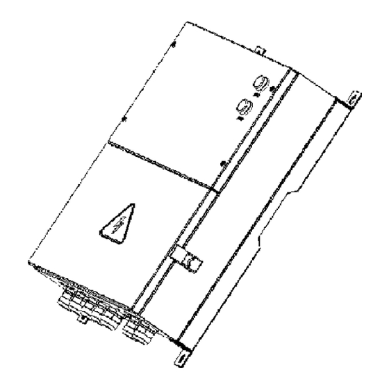
rectifier voltage is 1.414*380V≈537.3V,and the system was designed used 18 pieces panels which is 30V(Vmp),so Vmp is 30*18=540V.if the rectifier voltage is more different from Vmp , the power of solar will not be used in maximum mode. 2.2 Product’s Introduction 2.2.1 Appearance Figure 2-2 Appearance of Power Pack Table 2-1 Power Pack appearance information table... -
Page 11: Production Dimensions
Table 2-3 Power Pack dimension table Model Width (mm) Height(mm) Depth(mm) Net weight(kg) JNPH3AR-S 2.2.3 Product Name The way of product naming, take JNPH3AR-S for example Optimization upgrading Functional unit of system Company name Used for 30kw to 37kw H series System name Power level... -
Page 12: Power Pack Unpacking
According to the packing list to check whether all the parts is correct and in ● good condition If any damage is found, please contact Hefei JNTECH New Energy Co., Ltd. or the transportation company. Please keep well the photos taken at the damaged parts and we’ll provide you with best and fastest services. -
Page 13: Identify Power Pack
The nameplate in the side of Power Pack, and it shows the Power Pack model, some important parameter and certificate mark. Figure 3-2 Power Pack nameplate Table3-2 Nameplate information table Description JNTECH Logo and name. Power Pack model and parameter information. Company and website. Manufacturing code. -
Page 14: Installation Procedure
4 Installation procedure 4.1 Prepare Installation Tools The following tools will be needed during Power Pack installation and wire connection. You also can choose the right tools according to your own experience. Table 4-1 Installation tools list Recommend Sketch map Name Function Specification... -
Page 15: Installation Site Required
internal 3.5mm Used for cable connecting of AC hexagonal input side wrench 4.2 Installation Site Required Power Pack installation site environment has very important influence to the safe operation, the performance and life of the Power Pack. Choose the right installation site before install the Power Pack. All installation must comply with local standards. - Page 16 maximum angle of 10°. Do not install Power Pack tilted forwards. ● Never install the Power Pack horizontally. ● √ √ × 。 Min 80 Figure4-1 Installation directions Do not install the Power Pack in a place where children can touch. ●...
-
Page 17: Installation Of Power Pack
Diameter 10+1/0, depth 60+5/-0. Through expansion bolt to fix the bracket to the wall Figure 4-4 JNPH3AR-S Installation hole position figure Step 3: Hang the Power Pack four hangers to the fixed expansion bolt, tighten bolt with wrench. -
Page 18: Electrical Connection
5 Electrical Connection After the mechanical installation of Power Pack being finished, the electrical connection can be carried out. Following are the operation rules that need to be followed. Warning! All the electrical connection must meet local electrical connection ● standard. - Page 19 1. PV INPUT terminals connection Open the cover through the lock catch on right bottom of Power Pack. PV connecting terminals are waterproof. Put the cable through terminal block, and crimp the end into cold-pressed terminals, then finish the connection in accordance with the PV+ and the PV-. Operation Instruction Operation Demonstration 1....
- Page 20 Noted! PV+ waterproof terminals are on top of the panel, while the lower are Warning! Before connecting the PV array to the Power Pack, ensure its earth impedance is not less than 1Mohm. Warning! The positive and negative polarities of PV arrays cannot be inversely connected to Power Pack.
-
Page 21: Cable Selection
DC side (Input and Output) Power AC side Pack PV+、PV-、DC+、DC- JNPH3AR-S 5.3 Connector Disassembling Disassembling of Waterproof Joint Connector Please refer to the following diagram, using M8 screwdriver to remove the cold-pressed terminals from the terminal board or terminal row, rotating the nut in counterclockwise to remove the waterproof terminal cap. -
Page 22: Power Pack Commissioning
6 Power Pack Commissioning 6.1 Inspection before Commissioning PV Arrays Before operating the Power Pack, make sure PV arrays’ positive and negative polarities are connected correctly. Otherwise, the damage may be caused to Power Pack. Make sure that the open-circuit voltage of PV arrays do not exceed the max. - Page 23 Figure 2-5 Location of Dial Switch Note: Above photo shows that Power pack- JNPH3AR-S matching with Solar Pumping Inverter- JNP37KH. Table 6-1 Power Pack matching to Solar Pumping Inverter Dial Location Model No.of Model No.of Solar Pump Power Pack Inverter...
- Page 24 0.6. The access time of utility grid power can be controlled by setting the two button keys. Note: As shown in above setting, eg, JNPH3AR-S matching to JNP37KH, factor a=0.6,when PV power less than 37000*0.6=22200W, utility grid power will auto access to power pack as complementary energy to...
- Page 25 Table 6-2 Utility Grid Power Access Factor Dial location a Factor Down Down Down Down After the above steps being finished, when access to Utility Grid and PV energy, system system will work automatically. 6.2.3 Working Status Indication of Power Pack Indicator lights can display various colors and corresponding system working status.
- Page 26 Red Flash The voltage low, Raditor overheat/Temperature sensor fault, Utility Grid Power is withdrawn. After finishing the above steps, please wait for initialization. Close AC input side circuit breaker, waiting for about 1~2 seconds till Power Pack power indicator light, check whether the Solar Pumping Inverter power led and its LCD are light or not.
-
Page 27: Common Troubleshooting And Maintenance
7 Common troubleshooting and maintenance 7.1 Troubleshooting The following table lists the typical state of fault and treatment scheme: Table7-1 Exception handling operation table. Phenomena Cause value Troubleshooting Solar Pumping 1. Power Pack was 1. Properly wire connection between Power Pack Inverter’s power not connected with and Solar Pumping Inverter... -
Page 28: Maintenance
“PV” indicator The voltage of PV Please check the voltage, and confirm the light is yellow. is low. voltage is higher than 400V, and solve it. 7.2 Maintenance Please check and ensure the Power Pack is not charged before any maintenance. -
Page 29: Appendix
8 Appendix Quality Assurance The product malfunction in the warranty period, Hefei Jntech New Energy Co., LTD. will be free repair or replacement products. The warranty period take the contract as a standard. Evidence During the warranty period, customers should provide the invoices for the purchase of products and date.
Need help?
Do you have a question about the JNPH3AR-S and is the answer not in the manual?
Questions and answers