
Related Manuals for Emerson Rosemount 140


Summary of Contents for Emerson Rosemount 140
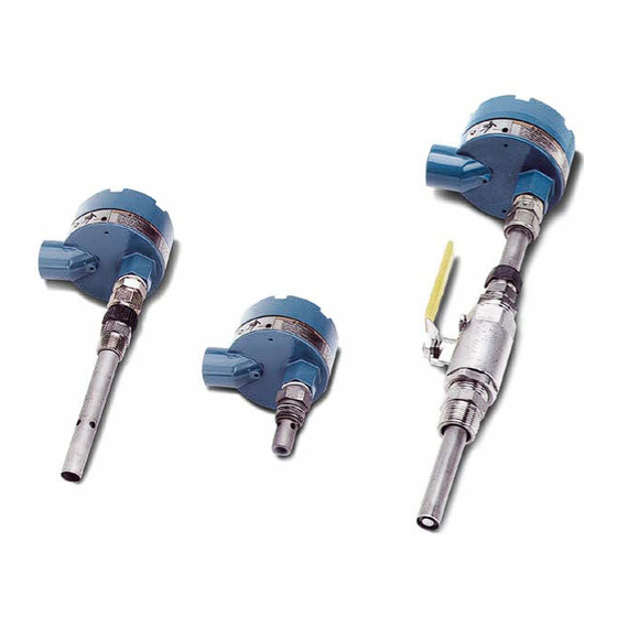
- Page 1 Quick Start Guide 00825-0100-3140, Rev AA May 2020 ™ Rosemount 140/141/142 Contacting Conductivity Sensors...
- Page 2 • Read all instructions prior to installing, operating, and servicing the product. • If you do not understand any of the instructions, contact your Emerson representative for clarification. • Follow all warnings, cautions, and instructions marked on and supplied with the product.
-
Page 3: Table Of Contents
Restrict physical access by unauthorized personnel to protect end users’ assets. This is true for all systems used within the facility. Contents Specifications..........................5 Installation........................... 9 Wire Rosemount 140, 141, and 142 sensors................14 Retract and insert the Rosemount 141 sensor................18 Remove and reinstall the Rosemount 142 sensor............... 22 Calibrate and maintain....................... 23 Troubleshoot..........................30 Accessories.......................... - Page 4 Quick Start Guide May 2020 Emerson.com/Rosemount...
-
Page 5: Specifications
May 2020 Quick Start Guide Specifications Table 1-1: Rosemount 140 Contacting Conductivity Sensor Specifications Cell constants 0.1 and 1.0/cm (nominal, to within ±5%) Wetted materials Electrodes 316 stainless steel Body 316 stainless steel Insulator Polyetheretherketone (PEEK) ® O-rings Viton Temperature range Standard 32 to 302 °F (0 to 150 °C) - Page 6 PEEK (high temperature option) PCTFE (low temperature option) O-rings Viton Temperature and pressure Figure 1-1. Vacuum At 1.6-in. Hg (5.2 kPa), air leakage is less than 0.005 SCFM (0.00014 m /min.) Junction box Cast aluminum Process connection ¾-in. (25.4 mm) MPT Emerson.com/Rosemount...
- Page 7 May 2020 Quick Start Guide Table 1-3: Rosemount 142 Contacting Conductivity Sensor Specifications (continued) Weight/shipping weight 2 lb./3 lb. (1.0 kg/1.5 kg) Weights rounded up to nearest whole lb. or 0.5 kg. Figure 1-1: Rosemount 141 and 142 Sensor Pressure/Temperature Graphs A.
- Page 8 Quick Start Guide May 2020 Figure 1-2: Performance Specifications: Contacting Conductivity - Recommended Range Emerson.com/Rosemount...
-
Page 9: Installation
May 2020 Quick Start Guide Installation Unpack and inspect Procedure 1. Inspect the outside of the carton for any damage. 2. If damage is detected, contact the carrier immediately. 3. Inspect the hardware. 4. Make sure all the items in the packing list are present and in good condition. - Page 10 Insert the sensor. Procedure 1. Install the sensor in either a 1-in. (25.4 mm) national pipe thread (NPT) weldalet or in a 1-in. (25.4 mm) pipe tee. 2. Remove the plastic shipping cap from the sensor. Emerson.com/Rosemount...
- Page 11 May 2020 Quick Start Guide 3. Screw the 1-in. (25.4 mm) hex nipple into the weldalet or pipe tee. Use pipe tape on the threads. Figure 2-2. Figure 2-2: Install with Ball Valve Kit (PN 23724-00) A. Radius of ball valve kit B.
- Page 12 2. Remove the plastic shipping cap from the sensor. 3. Screw the sensor into the fitting. Use pipe tape on the threads. Figure 2-3. Figure 2-3: Install Rosemount 141 Sensor A. Flow B. Sensor C. Tee D. Weldalet E. Process piping Emerson.com/Rosemount...
- Page 13 May 2020 Quick Start Guide Install Rosemount 142 sensor Procedure 1. Install the sensor in a ¾-in. (25 mm) national pipe thread (NPT) weldalet or in a 1-in. (25.4 mm) pipe tee. Figure 2-4. Figure 2-4: Install 142 Sensor A. Flow B.
-
Page 14: Wire Rosemount 140, 141, And 142 Sensors
Figure 3-1 shows wiring connections in the junction box. Rosemount 141 and 142 sensors have one gray wire (shown). The Rosemount 140 sensor has two gray wires attached to the terminal. Figure 3-1: Sensor Junction Box Wiring Table 3-1: Wire Color and Connections in Sensor... - Page 15 May 2020 Quick Start Guide Figure 3-2: Rosemount 140/141/142 Sensor Wiring to Rosemount 1056, 56, and 1057 Transmitters Table 3-2: Rosemount 140/141/142 Sensor Wiring to Rosemount 1056, 56, and 1057 Transmitters Terminal number Wire color Connects to White RTD return...
- Page 16 Quick Start Guide May 2020 Figure 3-3: Rosemount 140/141/142 Sensor Wiring to Rosemount 1066 Transmitter Table 3-3: Rosemount 140/141/142 Sensor Wiring to Rosemount 1066 Transmitter Terminal block number Wire color Connects to Receive B Receive A Clear R shield Gray...
- Page 17 May 2020 Quick Start Guide Figure 3-4: Rosemount 140/141/142 Sensor Wiring to Rosemount 5081 Transmitter Table 3-4: Rosemount 140/141/142 Sensor Wiring to Rosemount 5081 Transmitter Terminal Wire color Connects to Terminal Wire color Connects to number number Reserved Drive shield...
-
Page 18: Retract And Insert The Rosemount 141 Sensor
CAUTION Make sure the process O-ring is clean, lubricated, and in place before installing the center. Replace if worn. CAUTION Do not open the ball valve yet. CAUTION The system pressure must be less than 100 psig (791 kPa). Emerson.com/Rosemount... - Page 19 May 2020 Quick Start Guide Procedure 1. Thread the sensor compression fitting body into the reducing bushing in the rear of the ball valve and tighten. CAUTION Damage to the sensor could result. Do not push past this point. WARNING If the sensor comes free of the valve, refer to Figure 2-2 Figure...
- Page 20 Quick Start Guide May 2020 Figure 4-1: Rosemount 140 with Ball Valve Kit (PN 23724-00) A. Junction box cover B. Junction box compression fitting (PN 931020) C. Sensor compression fitting nut, included in kit (PN 23730-00) D. Polyetheretherketone (PEEK) split ring (inside) E.
- Page 21 May 2020 Quick Start Guide 4. Position the entire sensor for easy access to the ball valve handle, sensor compression fitting nut, and junction box terminal block. 5. Tighten sensor compression fitting nut. CAUTION For initial installation of the sensor, tighten the compression fitting nut 1¼...
-
Page 22: Remove And Reinstall The Rosemount 142 Sensor
The sensor tube takes a permanent set and could become weakened if the new set is adjacent to the original set. Be sure the sensor is in the original position. 2. Tighten the sensor compression fitting ¼ to ½ turn after it is finger tight. Emerson.com/Rosemount... -
Page 23: Calibrate And Maintain
Calibrate and maintain Calibrate the sensor Emerson does not calibrate the Rosemount 140/141/142 sensors at the factory. The cell constant on the label is a nominal value only. The true cell constant can differ from the nominal value by as much as ±five percent. - Page 24 No temperature correction is perfect. If the assumptions behind the algorithm do not perfectly fit the solution being measured, the temperature-corrected conductivity will be in error. b. If the temperature measurement itself is in error, the corrected conductivity will be in error. Emerson.com/Rosemount...
- Page 25 May 2020 Quick Start Guide The purpose of calibrating the sensor is to determine the cell constant. To minimize the error in the cell constant, eliminate all sources of avoidable error, e.g., temperature compensation. 4. Keep tubing runs between the sensors short and adjust the sample flow as high as possible.
- Page 26 Procedure Take a sample of the process liquid, measuring its conductivity using a reference instrument and adjusting the reading from the process transmitter to match the measured conductivity. Emerson.com/Rosemount...
- Page 27 May 2020 Quick Start Guide Take the sample from a point as close to the process sensor as possible. Keep temperature compensation turned on. There is likely to be a lag time between sampling and analysis, so temperature is likely to change. Be sure the reference and process instruments are using the same temperature correction algorithm.
- Page 28 You can also use isopropyl alcohol to remove oily films. Avoid using strong mineral acids to clean conductivity sensors. Check the Rosemount 140 retraction restraint The integrity of the Rosemount 140 will become compromised if the flared tip of the electrode is allowed to blow out against the compression fitting body.
- Page 29 May 2020 Quick Start Guide 2. Remove the nylon ferrule and snap ring and discard them. Remove and save the junction box compression fitting nut. 3. Slide off the sensor compression fitting nut and set aside for reuse. Slide off the remaining polyetheretherketone (PEEK) ferrule and split ring and discard them.
-
Page 30: Troubleshoot
Check temperature element for open or short circuits. Figure 7-1. Figure 7-1: Checking the Temperature Element A. Resistance temperature device (RTD) B. Terminal strip in sensor junction box C. Orange D. Red E. Gray Potential cause Sensor is not in process stream. Emerson.com/Rosemount... - Page 31 May 2020 Quick Start Guide Recommended action Submerge sensor completely in process stream. Potential cause Sensor has failed. Recommended action Perform isolation checks. Figure 7-2. Figure 7-2: Checking the Continuity and Leakage A. Orange B. Inner C. Outer D. Gray Noisy reading Potential cause Sensor is improperly installed in process stream.
- Page 32 See transmitter Reference Manual. Sluggish response Potential cause Electrodes are fouled. Recommended action Clean electrodes. Potential cause Sensor is installed in dead area in piping. Recommended action Move sensor to a location more representative of the process liquid. Emerson.com/Rosemount...
- Page 33 May 2020 Quick Start Guide Check the temperature element Procedure Disconnect leads and measure resistance shown. The measured resistance should be close to the value in the following table. Temperature (°C) Resistance in ohms Pt 100 100.0 103.9 107.8 111.7 115.5 119.4 Figure...
-
Page 34: Accessories
Conductivity standard SS-5A, 1000 µS/cm, 1 gal. (3.78 L) 05000705464 Conductivity standard, SS-1, 1409 µS/cm, 32 oz. (0.95 L) 05000709672 Conductivity standard, SS-1A 1409 µS/cm, 1 gal. (3.78 L) Table 8-2: Rosemount 140 Sensor Accessories Part number Description 23724-00 Ball valve kit 23730-00 Process compression fitting, ¾-in. - Page 35 May 2020 Quick Start Guide Quick Start Guide...
- Page 36 LinkedIn.com/company/Emerson- Automation-Solutions The Emerson logo is a trademark and service mark of Emerson Electric Co. Rosemount is a Twitter.com/rosemount_news mark of one of the Emerson family of companies. Facebook.com/Rosemount All other marks are the property of their Youtube.com/RosemountMeasurement respective owners.
Need help?
Do you have a question about the Rosemount 140 and is the answer not in the manual?
Questions and answers