Table of Contents
Troubleshooting

Subscribe to Our Youtube Channel
Related Manuals for Dometic MCS-CTRL


Summary of Contents for Dometic MCS-CTRL
- Page 1 MARINE CONTROL UNITS Smart Touch Cabin Control Installation and Operation Manual ..2 WARNING Cancer and Reproductive Harm www.P65Warnings.ca.gov Form No. L-3380 337767 | 2/20 | ©2020 Dometic Corporation...
-
Page 2: Table Of Contents
9 Control Parameters . . . . . . . . . . . . . . . . . . . . 16 Visit: www.dometic.com Understanding the General Settings . -
Page 3: Instructions
2 Intended Use Indicates additional information that is not related to physical injury. The Dometic Smart Touch Cabin Control is a microcontroller-based unit designed for use with direct expansion (DX), reverse-cycle air conditioning systems. 1 .3 Supplemental Directives... -
Page 4: General Information
3 General Information 3 .2 Tools and Materials Dometic recommends that the following tools and This section provides information on the features, tools, materials be used while installing the appliance: and high-level screen displays. -
Page 5: Understanding The Menu Screen Layout
Smart Touch Cabin Control General Information 3 .3 Understanding the Menu 3 .4 Understanding the Settings Screen Layout Screen Layout This screen is an example of a typical menu screen and This screen is an example of a typical setting screen. navigation buttons. -
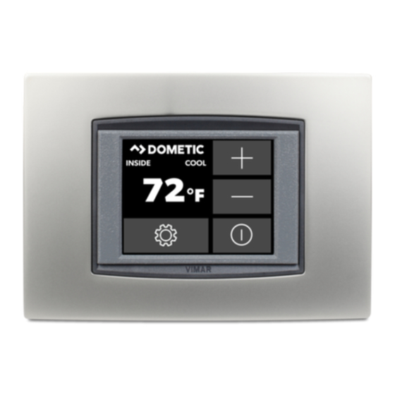
Page 6: Understanding The Home Screen
General Information Smart Touch Cabin Control 3 .5 Understanding the Home 3 .6 Understanding the Main Screen Screen This starting screen displays when the Smart Touch Enter from the home screen to access the most basic Cabin Control is turned on. functions as well as the menu for more options. -
Page 7: Specifications
Smart Touch Cabin Control Specifications No . Button Description Operational Specifications Temperature Displays the temperature based on the Environmental Indicator sensor indicator. Set Point Operating Range 65–85 °F Status Shows if a fault has occurred (18–29 °C) Ambient Temperature 5–150 °F Schedule Shows a schedule program is active and Operating Range Displayed (-15–66 °C) the specific times and days... -
Page 8: Wiring Diagrams
Wiring Diagrams Smart Touch Cabin Control 5 Wiring Diagrams WARNING: ELECTRICAL SHOCK . Turn the power off before opening the electrical The following diagrams show the component box. Failure to do so could result in death or serious connections for the direct expansion (DX) and chilled injury. -
Page 9: Understanding The Cw Wiring Diagram
Smart Touch Cabin Control Wiring Diagrams 5 .2 Understanding the CW Wiring Diagram SMX DISPLAYS ONLY For Humidistat For Changeover Switch 0-10 VDC Display Jacks (for 8- or 6-pin Display and Cables) Optional DC Blower Inside Temperature Sensor Jack Required Water-In Temperature Sensor Optional Water-Out Temperature Sensor Optional Outside Air Temperature Sensor Ground... -
Page 10: Installation And Setup
Installation and Setup Smart Touch Cabin Control 6 Installation and Setup – Select a location with freely circulating air where the temperature sensor can best sense average NOTICE: Do not use a screw gun and do not over- temperature. tighten the screws when mounting the display because –... -
Page 11: Installing The Optional Sensor Hardware
Smart Touch Cabin Control Installation and Setup 1. Mount the sensor in the return-air stream behind the opening of the return-air grille. 2. Plug the 6-pin connector cable into the inside jack #J3 in the upper-left corner of the circuit board. 6 .3 .2 Outside Air Temperature Install this optional sensor to monitor the outside air temperature (OAT). -
Page 12: Commissioning The System
Commissioning the System Smart Touch Cabin Control 2. Strap the sensor wire in place for strain relief and to 5. Press the fan icon, and verify that the fan is running prevent the sensor from being accidentally removed. and that there is steady airflow out of the supply air grille. - Page 13 Smart Touch Cabin Control Commissioning the System CW and DX - Commissioning Procedure CW only - Commissioning Procedure Screens 1 - 5 Screens 6 - 10 Screen Description Screen Description Low Fan Speed Test Auxiliary (Aux) Heater Test The fan is now energized at the above mentioned speed.
-
Page 14: Operation
Operation Smart Touch Cabin Control 8 Operation • By selecting cool mode, only cooling is supplied. • By selecting heat mode, only heating is supplied. This section describes the operating features. The cabin temperature in either mode is maintained Use the main menu settings to adjust the operating within 2 °F (1 °C) of the set point by default. -
Page 15: Understanding The Operating Modes
Smart Touch Cabin Control Operation • When a cycle is interrupted from the display panel by This behavior prevents small temperature overshoots pressing the power icon or changing the set point. from causing the system to switch between heating and cooling when it is not necessary. -
Page 16: Understanding The Fan Modes
Control Parameters Smart Touch Cabin Control 8 .3 .3 Fan-Only However, if the temperature is below 50 °F (10 °C), a heating cycle will begin. The heating cycle will continue The fan-only mode operates the fan for air circulation until the temperature reaches 50 °F (10 °C) or until the when no cooling or heating is desired. -
Page 17: Understanding The General Settings
Smart Touch Cabin Control Control Parameters 9 .1 Understanding the General The setting increments are in °F even when the control is set to display °C. Settings 5 Temperature Units (°F/°C/Auto) . Changes the This section describes the options available in general temperature units from the default F to C. - Page 18 The room temperature continues to display and the normal system operation is not affected. To clear and reset the timer, select general setting > filter hours setting. Dometic recommends checking the air filter at least every 500 hours of operation.
- Page 19 Smart Touch Cabin Control Control Parameters 14 General Settings Screen 5 15 General Settings Screen 6 13 Voltmeter Calibration . Displays a live reading of 16 Auto Fan Speed Temp Differential . Sets the the voltage as read by the power and logic circuit incremental differential (with cumulative steps) board.
- Page 20 Control Parameters Smart Touch Cabin Control 18 DX/CW Mode Selection . Choose “Set by Jumper” to preserve the status of the control board operation: – If the “Removed for CW” jumper on the main control board is not removed, the Smart Touch Cabin Control will operate in DX mode.
-
Page 21: Settings
Smart Touch Cabin Control Control Parameters 60% (default) relative humidity (RH). The range of There are two different failsafe levels: adjustment is 50% to 80% RH. – Faults Not Detected . Provides minimal failsafe • The electric heater cycles on and off to maintain protections and is recommended during initial the set point while the bypass valve opens to start up or troubleshooting. - Page 22 Control Parameters Smart Touch Cabin Control – If the voltage drops and remains below the Installing an optional alternate air temperature specified setting for five minutes, the Smart sensor (located in the return-air path) greatly Touch Cabin Control will shut down and the low increases the effectiveness of the de-icing AC voltage fault will display.
- Page 23 9 .3 Understanding the CW Choosing disabled (use caution) should only be Operational Settings done when advised by Dometic Customer Service. As with all faults, a system lockout (sustained This section describes the menu screens and the shutdown) will occur after the fourth consecutive operational settings available for the CW system.
-
Page 24: Settings
Control Parameters Smart Touch Cabin Control Water Temperature Differential 2 Water Temp Differential . Sets the temperature differential between the ambient air temperature Water Temperature Differential Valve Auxiliary and the hydronic water temperature that controls in °F Heater the water valve. For example, selecting 10 °F (-12 °C) Default is 15 °F (-9 °C) opens the valve when the water temperature is 10 °F 22 °F (-6 °C) -
Page 25: Understanding The Program Scheduler
> save. If the battery drains, there is no visible indication on the If you have any reason to contact Dometic about display during a normal power up. Immediately upon a subsequent AC power down and power up, the user the system or programming the control, you must will be prompted to set the date and time. -
Page 26: Understanding The Date/Time Menu
Control Parameters Smart Touch Cabin Control 24 Program Scheduler Screen 2 26 Program Scheduler Screen - Date and Time Submenu 2 4 - 7 Program: Day of the week (Seven programs) To access the date/time menu, select main menu, date/ time menu, and the setting to modify. - Page 27 Smart Touch Cabin Control Control Parameters 27 System Menu Screen 1 28 System Menu Screen 2 1 Firmware Version . Displays the firmware version. 4 Display Lock . Adjusts the display locking settings. To access, (such as “A23”), go to menu, system See section “Display Lock Submenus”...
- Page 28 Control Parameters Smart Touch Cabin Control 4 Sleep Mode Text Color . Select from 126 different text colors to display during sleep mode. 30 System Menu Screen - Sleep Mode Settings Submenu 2 32 System Menu Screen - Sleep Mode Setting - Custom Logo The available sleep mode settings are below.
-
Page 29: Understanding The Troubleshooting/Commissioning Screens
Smart Touch Cabin Control Control Parameters If the system enters sleep mode, the PIN entry will be required again to re-access the same level. The PIN entry will also be required again if this level setting is changed or if the display is AC power cycled. 35 Troubleshooting/Commissioning Screen 34 System Menu Screen - Change Pin Submenu –... -
Page 30: Understanding The Fault Handling
Control Parameters Smart Touch Cabin Control 9 .9 Understanding the Fault 2 Help & Information. Describes potential faults. Handling, History & Run Hours – Fault Help Lookup . Choose one of the help topics integrated in the software. This section describes the fault and run histories. •... - Page 31 Smart Touch Cabin Control Control Parameters When used with the optional auxiliary heat sensor, the fan remains on for four minutes after the heater cycles off even if the fan is set to cycled operation. 41 Compressor Run Hours 2 Compressor Run Hours . Displays the number of compressor run hours.
-
Page 32: Navigation Trees
Control Parameters Smart Touch Cabin Control 9 .10 Navigation Trees This section provides a visual representation to navigate the system options. 9 .10 .1 Main Menu Navigation Program Program Scheduler Mode Cool/Heat/Auto/AuxHeat/ AutoAuxHeat/Dehumidify Scheduler Mode On/Off Temp # °F/RH % Program Mon–Fri Hour Program Sat–Sun... - Page 33 Smart Touch Cabin Control Control Parameters 9 .10 .2 Control Parameters Navigation General Settings High Fan Speed 95 [35–95] Medium Fan Speed 61 [32–85] Low Fan Speed 50 [30–75] Inside Temp Calibration ±50 °F or ±25 °C Temperature Units Auto [Auto/°F/°C] Reversed Fan SPD in Heat On [On/Off] Aux Heat Option...
- Page 34 Control Parameters Smart Touch Cabin Control 9 .10 .3 System Settings Navigation Display Setup Display Brightness 100% [5–100] % Background Color Select color Button Text Color Select color Button Inside Color Select color Button Border Color Select color Data Block & Title Colors Select color System Menu Firmware Version...
-
Page 35: Maintenance
Smart Touch Cabin Control Maintenance 10 Maintenance 10 .3 Checking the Seawater Strainer – DX Only This section describes routine activities to maintain properly working system components. Ensure the pump receives adequate seawater flow. To maintain proper flow: WARNING: ACID HAZARD . Failure to obey the following warnings could result in death or 1. -
Page 36: Winterizing The System - Dx Only
Troubleshooting Smart Touch Cabin Control 11 Troubleshooting 10 .5 Winterizing the System – DX Only WARNING: ELECTRICAL SHOCK HAZARD . Failure to obey the following warnings could Any winterization method that causes the antifreeze result in death or serious injury: solution to flow downward is the method of choice. - Page 37 Smart Touch Cabin Control Troubleshooting 11 .1 General Troubleshooting Problem Possible Causes Recommended Solution The system does The air conditioning unit circuit breaker is off. Turn on the air conditioning unit circuit breaker at the ship’s panel. not power up. The display is not turned on.
- Page 38 Troubleshooting Smart Touch Cabin Control Problem Possible Causes Recommended Solution The fan does The digital control is set for either fan cycling Change the fan operation to continuous fan operation or fan cycling with not run or runs with compressor or for continuous fan compressor.
- Page 39 Smart Touch Cabin Control Troubleshooting Problem Possible Causes Recommended Solution The pump does A high-pressure fault may be present. See “A high-pressure fault is present” in this table. not run. The compressor A relay on the circuit board has shorted Call service to verify and replace the board.
- Page 40 Troubleshooting Smart Touch Cabin Control Problem Possible Causes Recommended Solution The air The display is experiencing a power Perform a factory reset of the display: conditioning unit interruption, voltage frequency fluctuation, 1. Turn the power off. does not respond electromagnetic interference from other 2.
-
Page 41: Disposal
13 .1 United States and Canada 13 .2 .2 New Zealand Only This warranty policy is subject to the conditions and LIMITED WARRANTY AVAILABLE AT WWW.DOMETIC. guarantees which are mandatory as implied by the COM/WARRANTY. Consumer Guarantees Act 1993(NZ). - Page 42 Smart Touch Cabin Control...
- Page 43 Smart Touch Cabin Control...
- Page 44 YOUR LOCAL YOUR LOCAL DEALER SUPPORT SALES OFFICE dometic .com/dealer dometic .com/contact dometic .com/sales-offices A complete list of Dometic companies, which comprise the Dometic Group, can be found in the public filings of: DOMETIC GROUP AB Hemvärnsgatan 15 SE-17154 Solna Sweden...
Need help?
Do you have a question about the MCS-CTRL and is the answer not in the manual?
Questions and answers